Transcription of Chapter1 Dimensioning Tol General - Engineers Edge
1 geometric BoundariesGeometric BoundariesInterpretation and Applicationof geometric Dimensioning and tolerancing (Using the Customary Inch System)Based on ASME and Illustrated byKelly L. BramblePublished by: Engineers Edge510 N. Crosslane RoadMonroe, Georgia All Rights ReservedDATUM AXISDATUM AXISDATUM AXISDATUM ORIGIN (0,0,0)90v90v90vDATUM book is written for those individuals within the design, drafting, engineering and manufacturing fields that desire a practical guide for the interpretation and application of geometric Dimensioning and tolerancing . I have deliberately directed my efforts for technical professionals applying geometric Dimensioning and tolerancing and attempted to comprehensively cover the concepts and applications that are and will be the most relevant within industry today and the future. The choice of examples are those which represent typical applications and may be combined as applicable to create products. Much of the text material has been organized so that the topics appear and build the necessary knowledge required to proceed to the next subject book is dedicated to my children, Nathan and L.
2 BrambleCopyright 2002, 2003, 2004, 2005, 2006, 2007 All right reserved. No part of this book may be reproduced or transmitted in any form or by any means, electronic or mechanical, including photocopying, recording, or any information storage and retrieval system, without permission in writing from the following documents have been used as reference material (cited and not cited).ASME , Dimensioning and , Dimensioning and , Dimensioniing and TolerancingANSI , Dimensioning and TolerancingInternational Standards Institute, ISO/R1101-1969, & Associated DocumentsANSI , Preferred Metric Limits and FitsANSI , Machine tapers Self Holding and Steep Taper SeriesANSI/ASME , Surface Texture (Surface Roughness, Waviness, and Lay)ANSI , Measurement of Out-of-RoundnessANSI , Involute Splines and Inspection, Inch VersionANSI , Metric Module, Involute SplinesANSI/ASME , KnurlingANSI , Twist DrillsANSI , Drawing Sheet Size and FormatASME , Line Conventions and LetteringASME , Mathematical Definition of Dimensioning and tolerancing , Screw Thread RepresentationANSI , Screw Thread Representation (Metric Supplement)ANSI , Gear Drawing Standards Part 1: For Spur, Helical, Double Helical, and RackANSI , Gear and Spline Drawing Standard Part 2.
3 Bevel and Hypoid GearsASME , Castings and ForgingsANSI , Surface Texture SymbolsANSI/IEEE 268-1992, Metric PracticeANSI/ASME , Gages and Gaging for Unified Inch Screw ThreadsANSI (R1987), Inspection of WorkpiecesASME , AbbreviationsASME , Multiview and Sectional View DrawingsEngineers Edge 2000 - 2007, Solutions by Design, Kelly Bramble, Design for Manufacturing 2006 - 2007, Kelly of Table of How the geometric Dimensioning and tolerancing System , Features and Control Frame, Rule #2 & and Limit Tolerance General Overview and Common Symbols ASME Dimensioning and tolerancing General Rules Limit General Dimensioning System Limit Limit tolerancing , Square - Round Tolerance Zone Contrast and Implied 90 Degree Angle, Expressing Limit Dimension and Tolerance Expression Millimeter Tolerances and Inch Tolerances and Angular Dimensioning and Slotted holes, Arcs, Countersink Counter bored Holes, Countersink on curved Internal External Chamfers, Rectangular Coordinate Rectangular Coordinate Dimensions in Tabular Form, Polar Repetitive Flat Taper.
4 Conical Statistical Dimension Origin, Screw Threads Tolerance Angular Surface Defined by Limit and Angle Gears and Splines, Controlled Radius, Radius Features With and Without Material Condition, MMC, Rule #1, Envelope Rule #1 Limitations, Datum Reference Frame, DRF Immobilization of component and Datum symbols and identification Datum identification features without Datum identification features with Datum associated with featurecontrol Datum feature, simulated datum, and theoretical datum Setup and inspection of datums, datum and dimensional measurement equipment Sequence of datum Sequence of datum features relates part to datum reference Cylindrical datum Parts with angular Development of datum reference Orientation of two datum planes through a Development of datum reference Partial datum surface as datum Multiple datum features, single Inclined datum View oriented datum reference Datum target point symbol, application Datum target Datum target Dimensioning datum Primary datum plane established by three datum target Primary datum plane established by two datum target points and one datum target line.
5 Step datum feature Datum target lines and Primary Datum Axis Established by Datum Target points on a Single Cylindrical Equalizing Secondary Datum Flatness applied on a unit Flatness applied on unit basis with overall Straightness applied in two Straightness of a surface (Cylindrical) of a feature of size @ Straightness of a feature of size @ Straightness per unit length With specified total straightness Circularity (Roundness) Perpendicularity - Perpendicularity Center Perpendicularity at MMC Internal Feature Center Perpendicularity External feature of Size Perpendicularity Internal feature of size Perpendicularity Threaded Hole or Inserts Projected Tolerance Parallelism Control of Two Hole Parallelism Hole Relative to Angularity Overview and Surface to Angularity Surface to Surface with Location Angularity Hole to Planar WorkshopTable of of Fundamental explanation of positional Differences between position tolerancing and limit Maximum material condition Least material condition External feature of size position tolerance boundaries with MMC Internal feature of size position tolerance boundaries with MMC External feature of size position tolerance boundaries with LMC modifier Internal Feature of Size Position Tolerance Boundaries with LMC Specification Zero positional
6 Tolerance at Position Tolerance at Positional Tolerance Axis and Surface Interpretation Surface Datum Positional Tolerance Axis and Surface Interpretation Surface Datum Positional Tolerance Axis Interpretation - Surface Datum s Positional Tolerance Surface Interpretation - Surface Datum Positional Tolerance Axis and Surface Interpretation - Thru Hole Datum Positional Tolerance Axis Interpretation Thru Hole Datum Positional Tolerance Surface Interpretation Thru Hole Datum Rectangular Coordinate Positional tolerance at MMC relative to hole and slot datum Bi-directional positional tolerancing , polar coordinate Different positional tolerance at each Circular pattern of Positional tolerance at MMC relative to datum feature center Positional tolerance at RFS of slots relative to surface datum Coaxial Coaxial (Concentric) Control of Multiple Hole-Counterbore Coaxial control of Hole pattern located perpendicular to cylindrical Holes Not Normal to Hole Pattern Located at Angle to Datum Reference Positional Tolerance at MMC of Spherical Positional Tolerance of Coaxial Holes of Same Least Material Condition Application Cylinder Wall Positional Tolerance for Coaxiality With Datum Feature referenced at Positional Tolerance for Coaxially with Feature Referenced at Zero MMC Relative to Datum Feature at Positional Tolerance - Thru Hole Datum s at MMCT able of of Positional Tolerance - Thru HoleDatum Composite Positional Profile of surface, bilateral Profile of Surface, unilateral (Inside) Profile of surface, unilateral (Outside)
7 Profile of surface, bilateral unequal Profile of surface, all Profile of Surface, Independent Form Profile of Surface, Boundary Profile Tolerance for Coplanar of Profile Composite Profile Circular Total Tolerance Tolerance Series Floating Fastener Fixed Fastener Tolerance Compensation for Projected Tolerance Zone FixedFastener Two Mating Coaxial/Coplanar Features at Tolerance Compensation for Projected Tolerance ZoneFixed Fastener Three Mating Coaxial/Coplanar Features at Position Tolerance calculation and Hole Pattern Position Tolerance Position Coordinate to LocationConversion Feature Drawing(Reduced Dimension Drawing) Implementation ConsiderationsApplicable documents, Design Drawing RequirementsDigital Model and Quality and inspection Change notice of Definitions and Terminology (Glossary) Comparison of ASME and ISO Symbols ( geometric Characteristics) Comparison of ASME and ISO Symbols ( General ) Dimensioning and tolerancing (GD&T) is an engineering drawing language used to communicate the physical limit requirements of a product object in two or three dimensional space.
8 The GD&T standard defines a collection of symbols and specific rules for defining specific characteristics, relationships, and feature latest standard on the subject of GD&T defined and in practice is the American Society of Mechanical Engineers (ASME) 1994 Dimensioning and tolerancing . The GD&T standard used internationally is the International Institute Standard (ISO) 1101:1983, Technical Drawings - Geometrical tolerancing and associated following are ISO standards that define GD&T requirements:ISO/129-Technical Drawings General PrinciplesISO/406-Technical Drawing Linear and Angular DimensionsISO/1101-Technical Drawings Geometrical TolerancingISO/1660-Technical Drawings ProfilesISO/2692-Technical Drawings Maximum Material ConditionIOS/2692:1998/DAM 1 Technical Drawings Least Material Condition ISO/3040-Technical Drawings Cones ISO/5458-Technical Drawings Positional tolerancing ISO/5959-Technical Drawings Datums and Datum SystemsISO/7083-Technical Drawings Symbols Proportions ISO/8015-Technical Drawings Fundamental Tolerance Principle ISO/10579-Technical Drawings Non-Rigid Parts IOS/10587-Technical Drawings Projected Tolerance Zones the geometric Dimensioning and tolerancing System WorksDimensioning and tolerancing is a means to communicate the geometry requirements of a particular part or assembly.
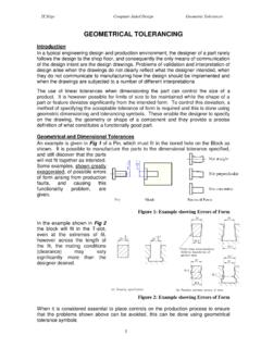
9 Depending on the function, feature relationships, manufacturing or definition requirements, one will then define the level or extent of details for the part. geometric Dimensioning and tolerancing (GD&T) standard ASME is a defined system of rules, symbols, and explicit requirements to fully delineate an objects geometric following are the more common reasons to apply GD&T principles: Part features are critical to function or inter-changeability. When functional gauging techniques are desired. When a common reference (origin) or datum is required to ensure communication is consistent between design, manufacturing and inspection. When a standard interpretation or tolerance is not already implied. Simplify tolerance analysis. Replace complex or long geometry requirement description notes with a single geometric symbol. trejmhgnilad_^SYMBOLCHACTERISTICTOLERANC E TYPEFORMPROFILEORIENTATIONLOCATIONRUNOUT FLATNESSSTRAIGHTNESSCYLINDRICITYCIRCULAR ITYPROFILE OF A SURFACEPROFILE OF A LINEPERPENDICULARITYPARALLELISMANGULARIT YPOSITIONCONCENTRICITYSYMMETRYTOTAL RUNOUTCIRCULAR RUNOUTFORINDIVIDUALFEATURESFOR INDIVIDUALOR RELATEDFEATURESFORRELATEDFEATURESG eometric Characteristics and SymbolsGeometric characteristic symbols are used to define a simple or complex feature requirement or relationship.
10 GD&T characteristics and categories are:See outside-back cover of this book for an expanded geometric characteristics AND tolerancing