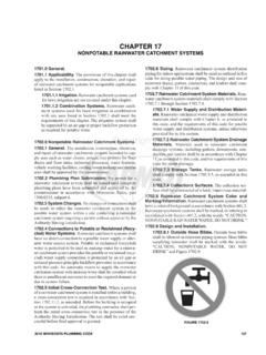
Transcription of CHAPTER7
1 CHAPTER 7. SANITARY DRAINAGE. Part I Drainage Systems. (1) For safe pans not less than four (4) pounds per square foot lb/ft2 ( 19 kg/m2) or one-sixteenth (1 16) of an Materials. inch ( mm) thick. Drainage Piping. Materials for drainage piping (2) For flashings or vent terminals not less than three 3. shall be in accordance with one of the referenced standards pounds per square foot lb/ft2 ( 15 kg/m2) or in Table 7 1 except that: inches ( mm) thick. (1) No galvanized wrought-iron or galvanized (3) Lead bends and lead traps shall be not less than one- steel pipe shall be used underground and shall be kept eighth (1 8) of an inch ( mm) wall thickness. not less than six (6) inches (152 mm) above ground. Ferrules and Bushings. (2) ABS and PVC DWV piping installations shall be installed in accordance with applicable standards Caulking Ferrules. Caulking ferrules shall referenced in Table 14-1 and Chapter 15 be manufactured from bronze or copper and shall be in Firestop Protection.
2 Except for individual single- accordance with Table 7-2 (a) family dwelling units, materials exposed within ducts Soldering Bushings. Soldering bushings T. or plenums shall have a flame-spread index of a shall be of bronze or copper in accordance with Table maximum of twenty-five (25) and a smoke-developed 7-2(b) index of a maximum fifty (50), when where tested in accordance with the Test for Surface-Burning Charac- teristics of the Building Materials. (See the Building Code standards based on ASTM E84 and UL 723). IN. (3) No vitrified clay pipe or fittings shall be used above ground or where pressurized by a pump or PIPE SIZE. INSIDE. DIAMETER. TABLE 7-2(a) CAULKING FERRULES. LENGTH MINIMUM WEIGHT EACH. R. (inches) (inches) lb. (pounds) oz. (ounces). (inches). ejector. They shall be kept not less than twelve (12) 2 21/4 41/2 1 0. inches (305 mm) belowground. 3 3 /4 41/2 1 12.
3 -P. (4) Copper tube for drainage and vent 1. piping shall have a weight of not less than that 4 41/4 41/2 2 8. of copper drainage tube type DWV. For SI units: 1 inch = 25 mm, 1 pound = kg, 1 ounce = Kg (5) Stainless steel 304 pipe and fittings shall not E. be installed underground and shall be kept not less than Caulking Ferrules (Metric). six (6) inches (152 mm) above ground. Pipe Size Inside Diam- Minimum Weight Each Length (mm). (6) Cast-iron soil pipe and fittings shall be listed (mm) eter (mm) (kg). R. and tested to comply in accordance with standards 50 57 114 referenced in Table 14-1 Such pipe and fittings 80 83 114 shall be marked with country of origin and identifica- P. tion of the original manufacturer in addition to any 100 108 114 markings required by referenced standards. TABLE 7-2(b) Drainage Fittings. Materials for drainage fittings SOLDERING BUSHINGS.
4 Shall be in accordance with the applicable standards refer- PIPE MINIMUM WEIGHT PIPE MINIMUM WEIGHT. enced in Table 7-1 of the same diameter as the piping SIZE EACH SIZE EACH. served, and such fittings shall be compatible with the type (inches) lb. (pounds) oz. (ounces) (inches) lb. (pounds) oz. (ounces). of pipe used. 11 4 0 6 21 2 1 6. Screwed Pipe. Fittings on screwed pipe 1 2 0 8 3 2 0. shall be of the recessed drainage type. Burred ends 1. shall be reamed to the full bore of the pipe. 2 0 14 4 3 8. Threads. The threads of drainage fittings For SI units: 1 inch = 25 mm, 1 pound = kg, 1 ounce = Kg shall be tapped so as to allow one-fourth (1 4) inch per Soldering Bushings (Metric). foot ( mm/m) grade. Minimum Type. Fittings used for drainage shall be of Pipe Size Pipe Size Minimum Weight Each Weight Each (mm) (mm) (kg). the drainage type, have a smooth interior water-way, (kg).
5 And be constructed so as to allow one-fourth (1 4) inch 32 65 per foot ( mm/m) grade. 40 80 Lead. See Table 14-1 Sheet lead shall be 50 100 not less than the following: UNIFORM PLUMBING CODE 131. SANITARY DRAINAGE. TABLE 7-1 MATERIALS FOR DRAIN, WASTE, VENT PIPE AND FITTINGS. UNDERGROUND ABOVE GROUND. BUILDING SEWER REFERENCED. DRAIN, WASTE, DRAIN, WASTE, REFERENCED. MATERIAL PIPE AND STANDARD(S). VENT PIPE AND VENT PIPE AND STANDARD(S) PIPE. FITTINGS FITTINGS. FITTINGS FITTINGS. ASTM D 1527, ASTM D 2661, ASTM D 2661, ABS (Schedule 40) X X X. ASTM D 2680 , ASTM D 2680. 1* 1*. ASTM F 628. ASTM C 428 , 1*. Asbestos-Cement X . ASTM C 14. 1*. Brass X ASTM B 43 . ASME , ASTM A 74, T. ASTM A 74, Cast-Iron X X X ASTM A 888, ASTM A 888, CISPI 301. CISPI 301. Co-Extruded ABS. (Schedule 40). X X IN X ASTM F 1488. ASTM D 2661, ASTM D 2680. 1*. R. ASTM D 2665, Co-Extruded PVC ASTM F 1488, X X X ASTM F 7941, (Schedule 40) ASTM F 891.
6 -P. ASTM F 1866. ASTM B 75, ASTM B 251, ASME , E. Copper (Type DWV) X X X. ASTM B 302, ASME ASTM B 306. R. Galvanized Malleable Iron X ASME Galvanized Steel X ASTM A 53 . P. ASTM D 1785, ASTM D 2665, PVC (Schedule 40) X X X ASTM D 2665, ASTM F 794 , 1*. ASTM F 794 ASTM F 1866. 1*. ASTM D 2683, ASTM D 3261, Polyethylene X ASTM F 714. ASTM F 1055, ASTM F 2206. Stainless Steel 304 X ASME ASME Stainless Steel 316L X X X ASME ASME Vitrified Clay (Extra X ASTM C 700 ASTM C 700. strength). For Bbuilding Ssewer applications. 1*. 132 UNIFORM PLUMBING CODE. SANITARY DRAINAGE. Fixture Unit Equivalents. Maximum Number of Fixture Units. Table 7-5. Trap Size. The unit equivalent of plumbing fixtures shows the maximum number of fixture units allowed shown in Table 7-3 shall be based on the size of the on any a vertical or horizontal drainage pipe, building trap required, and the unit equivalent of fixtures and drain, or building sewer of a given size; the maximum devices not shown in Table 7-3 shall be based on the number of fixture units allowed on any a branch interval of a size of trap or trap arm.
7 Given size; and the maximum length (in feet and meters) of Maximum drainage fixture units for a fixture trap and any a vertical drainage pipe of a given size. trap arm loadings for sizes up to four (4) inches (100 mm) Sizing per Appendix C. For alternate method of are as follows shall be in accordance with Table (a): sizing drainage piping, See Appendix LC. TABLE (a). MAXIMUM DRAINAGE FIXTURE UNITS FOR A Fixture Connections (Drainage). TRAP AND TRAP ARM Inlet Fittings. Drainage piping shall be provided with SIZE OF TRAP AND DRAINAGE FIXTURE. approved inlet fittings for fixture connections, correctly TRAP ARM (inches) UNIT VALUES (DFU). located according to the size and type of fixture proposed to be connected. 1 4 in. (32 mm) 1 unit Single Vertical Drainage Pipe. Two (2) fixtures 1. 11 2 in. (40 mm) 3 units set back-to-back, or side-by-side, within the distance allowed 2 in.
8 (50 mm) 4 units between a trap and its vent shall be permitted to be served by T. 3 in. (80 mm) 6 units a single vertical drainage pipe provided that each fixture wastes separately into an approved double-fixture fitting 4 in. (100 mm) 8 units having inlet openings at the same level. IN. Exception: On self-service laundries. Sinks and Dishwashing Machines. Pot sinks, For SI Units: 1 inch = 25 mm scullery sinks, dishwashing sinks, silverware sinks, commer- cial dishwashing machines, silverware-washing machines, Intermittent Flow. Drainage fixture units for inter- and other similar fixtures shall be connected directly to the drainage system. A floor drain shall be provided adjacent to R. mittent flow into the drainage system shall be computed on the rated discharge capacity in (gallons per minute) (gpm) the fixture, and the fixture shall be connected on the sewer side of the floor drain trap, provided that no other drainage (liters per second L/s) in accordance with Table 7 4 (b).
9 Line is connected between the floor drain waste connection -P. TABLE 7-4 (b). and the fixture drain. The fixture and floor drain shall be DISCHARGE CAPACITY IN GALLONS PER MINUTE (Liters per trapped and vented as required by this code. Second) FOR INTERMITTENT FLOW ONLY*. Joints and Connections. E. GPM (L/sec) FIXTURE UNITS. Types of Joints. Up to 71 2 Up to Equals 1 Fixture Unit Caulked Joints. Caulked joints for cast- iron R. Greater than 7 2 to 15. 1. ( to ) Equals 2 Fixture Units bell-and-spigot soil pipe and other similar joints shall be Greater than 15 to 30 ( to ) Equals 4 Fixture Units firmly packed with oakum or hemp and filled with Greater than 30 to 50 ( to ) Equals 6 Fixture Units molten lead to a depth of not less than one (1) inch ( P. mm). The lead shall be caulked thoroughly at the inside For SI units: 1 gallon per minute = L/s * and outside edges of the joint.
10 After caulking, the Note: Discharge capacity exceeding 50 gallons per minute ( ). finished joint shall not exceed one-eighth (1 8) of an inch ( mm) below the rim of the hub. No paint, varnish, or shall be determined by the Authority Having Jurisdiction. other coatings shall be permitted on the joining material Continuous Flow. For a continuous flow into a until after the joint has been tested and approved. drainage system, such as from a pump, sump ejector, air Caulked joints in cast-iron bell-and-spigot water piping conditioning equipment, or similar device, two (2) fixture shall be made with nontoxic materials. units shall be allowed for equal to each gallon per minute Cement Mortar Joints. Except for repairs (gpm) ( L/m L/s) of flow. and connections to existing lines constructed with such joints, cement mortar joints shall be prohibited on building sewers. Size of Drainage Piping.