Example: quiz answers
반도체및공정 - cheric.org
허가없이본수업자료의무단배포및사용을불허합니다. 1) 노광 (Photolithography) -사진에서렌즈로들어오는빛을감광재료에비춰
Tags:
Information
Domain:
Source:
Link to this page:
Documents from same domain
차세대 투명전극 소재의 종류와 특성 - cheric.org
www.cheric.org244 정문현⋅김세열⋅유도혁⋅김중현 공업화학, 제25 권 제3 호, 2014 (a) (b) Figure 2. (a) Schematic of graphene transfer process[14], (b) Graphene

GPC 분석에서 중요한 핵심포인트들 - cheric.org
www.cheric.org556 Polymer Science and Technology Vol. 19, No. 6, December 2008 1. 서론 고분자의 분자량 측정은 우리가 신체 검사시 제일 먼저 키와 몸무 게를 재는 것과 같이 고분자분야에서 가장 기본적이고 중요한 분석중
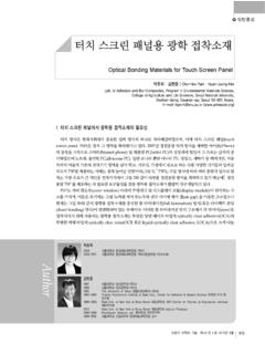
터치 스크린 패널용 광학 접착소재 - cheric.org
www.cheric.org일반총설 | 터치 스크린 패널용 광학 접착소재 314 Polymer Science and Technology Vol. 26, No. 4, August 2015 그림 1. TSP의 시장 전망.1 …

주사전자현미경의 기본원리와 응용(Part Ⅱ
www.cheric.org주사전자현미경의 기본원리와 응용(Part Ⅱ) KIC News, Volume 13, No. 1, 2010 53 Figure 3. 전자총 외부, Wehnelt 실린더, 텅스턴 필라멘트 사진.
Modified Soave-Redlich-Kwong Equations of State Applied …
www.cheric.orgThe Soave-Redlich-Kwong EoS (SRK) is probably the most wide- ly employed model to correlate and predict fluid properties and phase equilibria in the process industry.

Introduction to Safety in Chemical Process Industry
www.cheric.orgPetrochemicals, "Black Gold, Texas Tea": Form many useful products from petroleum by developing processes like catalytic cracking gasoline, lubricating oils, plastics, synthetic rubber, and synthetic fibers 9/28/2011 METU 39

Poly(lactic acid) 기반 생분해성 복합소재의 연구동향
www.cheric.orgPoly(ethylene terephthalate) 69 265 48–72 30–300 Poly(lactic acid) 45–60 150–162 21–60 2.5–6.0 Poly(butylene adipate-co-terephthalate) -34 115–125 21 670 Poly(caprolactone) -60 to -65 58–65 21–42 300–1,000 표 1. 비분해성 고분자와 생분해성 고분자의 열적, 기계적 물성 그림 1. PLA의 화학 구조 ...

Gene Cloning - CHERIC
www.cheric.org7 Basic Steps of Gene Cloning 1)A fragment of DNA , containing the gene to be cloned, is inserted into a circular DNA molecule (vector) Æ"Recombinant DNA molecule" or "Chimera" 2)The vector acts as a vehicle that transports the gene into a host cell (usually, bacterium) Æ possibly other types of living cell.
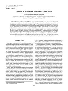
Synthesis of metal-organic frameworks: A mini review
www.cheric.orgMetal organic frameworks (MOFs) are a class of crystalline or-ganic-inorganic hybrid compounds formed by coordination of metal clusters or ions with organic linkers, in which bivalent or trivalent aromatic carboxylic acids or N-containing aromatics are commonly used to form frameworks with zinc, copper, chromium, aluminum,

P 129 Chapter 6. Transition Temperature
www.cheric.orgex> polystyrene (Mn=10000, Tg=88° C ) Polystyrene (Mn>50000, Tg=100 °C ) c) crosslinking increases the Tg of a polymer. Large shifts of Tg with increased cross-linking are observed, (ex) epoxy or phenolic thermosetting resin. d) The free volume of the polymer Vf. - free volume is the volume of the polymer mass not actually occupied by the
Related documents
“Making of a Chip”
download.intel.comPhotolithography Applying Photoresist – scale: wafer level (~300mm / 12 inch) Photolithography is the process by which a specific pattern is imprinted on the wafer. It starts with the application of a liquid known as photoresist, which is evenly poured onto the wafer while it spins. It gets its name from the fact that

Exposure of Photoresists - MicroChemicals
microchemicals.comAs the name photolithography already clearly expresses, the following exposure of photore-sists represents the main key process in microstructuring. The chemical processes occurring here in the resist fi lm result in an increased (positive resists) or reduced (neg-

Yield and Yield Management - Smithsonian Institution
smithsonianchips.si.edufollowed by photolithography errors, and material (wafer) defects (Figure 3-2). The dramatic decline in the contribution of people to particulate problems in the fab can be attributed to better education and train-ing, adherence to clean room disciplines, and less direct contact by the people due to more use of automation.

Silicon Wafer Processing
jupiter.math.nctu.edu.twphotolithography. Fabrication Semiconductor memory chips are manufactured in cleanroom environments because the circuitry is so small even tiny bits of dust can damage it. Class 1 and class 10 cleanrooms are typical. In a class 1 cleanroom, there is no more than 1 particle of dust in a cubic foot of air.
PROCESSING OF INTEGRATED CIRCUITS
www.me.nchu.edu.twPhotolithography •Uses light radiation to expose a coating of photoresist on the surface of the wafer Common light source in wafer processing is ultraviolet light, due to its short wavelength •A mask containing the required geometric pattern for each layer separates the light source from the wafer, so that only the portions of the ...

Photolithography - Wake Forest University
users.wfu.eduphotolithography uses optical radiation to image the mask on a silicon wafer using photoresist layers. • Other methods are electron beam, scanning probe, X-ray and XUV lithography. Steps Used in Photolithography • Surface cleaning • Barrier layer formation (Oxidation)
Photolithography - University of Washington
labs.ece.uw.eduPhotolithography • Photo-litho-graphy: latin: light-stone-writing • Photolithography is an optical means for transferring patterns onto a substrate. It is essentially the same process that is used in lithographic printing. • Patterns are first transferred to an imagable photoresist layer.

Photolithography Overview for MEMS
nanoscale.unl.eduPhotolithography is the process that defines and transfers a pattern onto a thin film layer on the wafer. In the photolithography process a light source is typically used to transfer an image from a patterned mask to a photosensitive layer (photoresist or resist) on a …

PHOTOLITHOGRAPHY OVERVIEW FOR MICROSYSTEMS
nanoscale.unl.eduJul 10, 2012 · Photolithography and MEMS v Microsystems (MEMS) fabrication uses several layers to build devices. v Each layer of this linkage system is a different component of the device and requires a different pattern. v Photolithography defines and transfers a pattern to each respective layer. MEMS Linkage Assembly