Transcription of Cisco UCS 6300 Series Fabric Interconnect Spec Sheet
1 Cisco SYSTEMSPUBLICATION HISTORY 170 WEST TASMAN DR. SAN JOSE, CA, 95134 REV 31, 2020 SheetCisco UCS 6300 SeriesFabric InterconnectCisco UCS 6300 Series Fabric Interconnect1 CONTENTSOVERVIEW .. 1 Cisco UCS 6332 32-Port Fabric Interconnect ..1 Cisco UCS 6332-16UP 40-Port Fabric Interconnect ..2 DETAILED FRONT VIEW .. 3 Power Supply LEDs .. 4 Management Port LEDs .. 5 DETAILED REAR VIEWS .. 6 Cisco UCS 6332 32-Port Fabric Interconnect Rear View ..6 Beacon and System Status LEDs .. 7 Lane Switch Button and Lane LEDs .. 7 System Environment LEDs .. 8 QSFP+ Port LEDs .. 8L1/L2 Port LEDs .. 9 Cisco UCS 6332-16UP 40-Port Fabric Interconnect Rear View .. 10 Lane Switch Button and Lane LEDs .. 10 Ethernet Port ( ports 1 16) LEDs .. 11 Cisco UCS 6300 Fabric Interconnect Series CAPABILITIES and FEATURES 12 CONFIGURING the Fabric Interconnect .. 14 SUPPLEMENTAL MATERIAL .. 34 Cisco UCS 6332 Port Numbering .. 34 Cisco UCS 6332 (Supported speed matrix).
2 35 Cisco UCS 6332-16UP Port Numbering .. 35 Cisco UCS 6332-16UP (Supported speed matrix) .. 36 Accessory Kit .. 36 LED Descriptions .. 37 Connectivity .. 385108 Blade Chassis Server Connectivity .. 38C- Series Rack-Mounted Server Connectivity .. 39 Blade Chassis Connection Types .. 41 TECHNICAL SPECIFICATIONS .. 43 Physical and Environmental Specifications .. 43 Power Supply Specifications .. 44 Transceiver Specifications .. 45 Cisco UCS 6300 Series Fabric InterconnectOVERVIEW1 OVERVIEWThe Cisco UCS 6300 Series Fabric Interconnects are a core part of the Cisco Unified Computing System, providing both network connectivity and management capabilities for the system. The Cisco UCS 6300 Series offers line-rate, low-latency, lossless 40-Gigabit Ethernet, Fibre Channel over Ethernet (FCoE), and Fibre Channel functions, as well as unified ports capable of either Ethernet or Fibre Channel Cisco UCS 6300 Series Fabric Interconnects provide the management and communication backbone for the Cisco UCS B- Series and C- Series servers.
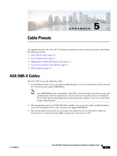
3 All servers attached to the Cisco UCS 6300 Series Fabric Interconnects become part of a single, highly available management domain. In addition, by supporting unified Fabric , the Cisco UCS 6300 Series provides both the LAN and SAN connectivity for all blades within its a networking perspective, the Cisco UCS 6300 Series uses a cut-through architecture, supporting deterministic, low-latency, line-rate 40-Gigabit Ethernet on all ports , switching capacity of up to Tbps, and 320-Gbps bandwidth per chassis, independent of packet size and enabled services. The product family supports Cisco low-latency, lossless 40-Gigabit Ethernet unified network Fabric capabilities, which increase the reliability, efficiency, and scalability of Ethernet networks. The Fabric Interconnect supports multiple traffic classes over a lossless Ethernet Fabric from the blade through the UCS 6332 32-Port Fabric InterconnectThe Cisco UCS 6332 32-Port Fabric Interconnect is a one-rack-unit (1RU) 40-GbE switch offering up to Tbps full-duplex throughput.
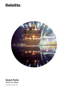
4 The switch has 32 40-Gbps QSFP+ ports , which operate as follows: ports 1 4 can operate as 40-Gbps QSFP+ ports , or as 4 x 10 Gbps SFP+ breakout ports , or can be optionally outfitted with Quad to SFP (QSA) adapters to provide 10 Gbps operation. ports 5 12 and 15 26 can operate as 40-Gbps QSFP+ ports , or as 4 x 10 Gbps SFP+ breakout ports , or can be optionally outfitted with Quad to SFP (QSA) adapters to provide 10 Gbps operation. ports 13 and 14 can operate as 40-Gbps QSFP+ ports . They cannot operate as 4 x 10 Gbps SFP+ breakout ports . ports 27 32 are dedicated 40 Gbps QSFP+ 32-port chassis is shown in Figure 1 Cisco UCS 6332 Fabric Interconnect (1RU)Front ViewRear ViewCisco UCS 6300 Series Fabric Interconnect2 OVERVIEWC isco UCS 6332-16UP 40-Port Fabric InterconnectThe Cisco UCS 6332-16UP 40-Port Fabric Interconnect is a 1RU 10-GbE, 40-GbE, and native Fibre Channel switch offering up to full-duplex throughput. The ports operate as follows: ports 1 16 operate as SFP+ Universal ports capable of operating at 1/10-Gbps fixed Ethernet or 4/8/16 Gbps Fibre Channel ports .
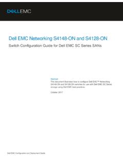
5 ports 17 34 operate as 40 Gbps QSFP+ ports or as 18 4 x 10 Gbps SFP+ breakout ports or can be optionally outfitted with QSA adapters to provide 10 Gbps operation. ports 35 40 operate as fixed 40 Gbps QSFP+ ports . The 40-port chassis is shown in Figure 2 Cisco UCS 6332-16UP Fabric Interconnect (1RU)Front ViewRear ViewCisco UCS 6300 Series Fabric InterconnectDETAILED FRONT VIEW3 DETAILED FRONT VIEWThe Cisco UCS 6332 and Cisco UCS 6332-16UP chassis look identical from the front, as shown in Figure 3 Front View of 6332 and 6332-16UP13051851321 Power supplies (two). AC versions and USB ports (see Figure 4)2 Fan modules (four) Figure 4 Connector and USB Ports305194 1 BCNSTS2200W AC1325461RJ45 network management port (10/100/1000 Mbps)4 USB port 22 USB port 15 Beaconing LED/button3RJ45 console port6 System status LEDC isco UCS 6300 Series Fabric Interconnect4 DETAILED FRONT VIEWF igure 5 Power Supply3051871200W AC211 Amber fault/error LED2 Green Power on LEDP ower Supply LEDsThe power supply LEDs are located on the left front portion of the power supply.
6 Combinations of states indicated by the Okay ()and Fault ()LEDs indicate the status for the module as shown in the Ta b l e 1 Table 1 power supply LED statesPower on LEDE rror LED StatusGreenOffPower supply is on and outputting power to the greenOffPower supply is connected to a power source but not outputting power to the switch power supply might not be installed in the supply is not receiving amberPower supply warning possibly one of the following conditions: High voltage High power Low voltage Power supply installed in chassis but not connected to a power source Slow power supply fanFlashing greenAmberPower supply failure possibly one of the following conditions: Over voltage Over current Over temperature Power supply fan failureCisco UCS 6300 Series Fabric InterconnectDETAILED FRONT VIEW5 Management Port LEDsThe management port LED states are shown in Ta b l e 2 Management Port LED StatesLED PositionLED StateDescriptionLeftOffNo linkSolid greenPhysical linkRightOffNo activityBlinking greenActivityCisco UCS 6300 Series Fabric Interconnect6 DETAILED REAR VIEWSDETAILED REAR VIEWSC isco UCS 6332 32-Port Fabric Interconnect Rear ViewFigure 6 is an overall rear view of the Cisco UCS 6332 Fabric 6 6332 32-port Fabric Interconnect Chassis Overall Rear View1 Control buttons, LEDs, and L1/L2 ports (see Figure 7)
7 2 ports 1 263 ports 27 32 Figure 7 is an detailed rear view of the Cisco UCS 6332 Fabric 7 6332 32-port Fabric Interconnect Chassis Detailed Rear View1L1 highly available port5 Beacon pushbutton/LED2L2 highly available port6 System status LED3 Lane switch 7 System environment LED4 QSFP+ lane LEDs LS4567132 Cisco UCS 6300 Series Fabric InterconnectDETAILED REAR VIEWS7 Beacon and System Status LEDsThe beacon and system status LED states are shown in Ta b l e 3 Beacon and System Status LED StatesLEDL ocationFunctionColorStateDescriptionBeac on LEDF ront and rearIdentify selected chassisBlueSolid on Chassis is selectedOffChassis is not selectedSystem status LEDF ront and rearSystem power/health during boot up and run timeGreenSolid onNormal operationOffSystem is powered offAmberOnSystem faultRedSolid onPower shut down by softwareBlinkingSecure boot validation has failedLane Switch Button and Lane LEDsThe lane switch button and lane LED states operate as follows: When none of the four vertical lane LEDs (apart from the button) are illuminated, 40 Gbps mode is in effect.
8 This is the default mode after bootup. In this mode, the LED on each individual QSFP+ port reflects 40 Gbps link status. When you first push the lane switch button, lane LED #1 is lit, and the LED on each individual QSFP+ port represents the lane 1 status of the port. When you push the button again, the lane LED #2 is lit, and the LED on each individual QSFP+ port represents the lane 2 status of the port. When you push the button again, the lane LED #3 is lit, and the LED on each individual QSFP+ port represents the lane 3 status of the port. When you push the button again, the lane LED #4 is lit, and the LED on each individual QSFP+ port represents the lane 4 status of the port. When you push the button the fourth time, 40 Gbps mode is back in effect (as in the first bullet in this list).If a 40 Gbps is not in breakout mode, if the link up, the LED on an individual QSFP+ port is green when all the lane LEDs are off and It is extinguished when you push the lane button to lane 1, 2, 3, or a port configured in breakout mode, the LED for an individual QSFP+ port is off when the lane LEDs are off (40 Gbps mode).
9 When you cycle the lane switch button, the LED for an individual QSFP+ port shows the status of the different 13 and 14 cannot operate as breakout ports , therefore, the QSFP+ port LEDs for those ports are always the same as the 40 Gbps mode UCS 6300 Series Fabric Interconnect8 DETAILED REAR VIEWSS ystem Environment LEDsThe system environment LED states are shown in Ta b l e 4 System Environment LED StatesLED StateDescriptionSolid AmberMinor fan alarm (one fan missing or failureSolid redMajor fan alarm (two more fans missing or failed, or fan direction mismatch)QSFP+ Port LEDsFigure 7 is an detailed view of a dual QSFP+ port and its 8 QSFP+ Port LEDsThe port LED states are shown in Ta b l e 5 QSFP Port LED StatesLED StateDescriptionYe l l o wEnabled (but SFP not inserted)GreenEnabled (and link is up)OffEnabled (but link not connected)Blinking yellowPower On Self Test (POST) failedBlinking yellowPort beacon enabledYe l l o wAdministrative (software shut down)Upper port LEDL ower port LEDC isco UCS 6300 Series Fabric InterconnectDETAILED REAR VIEWS9L1/L2 Port LEDsThe L1/L2 port LED states are shown in Ta b l e 6 L1/L2 Port LED StatesLED PositionLED StateDescriptionLeftOffNo linkSolid greenPhysical linkRightOffNo activityBlinking greenActivityCisco UCS 6300 Series Fabric Interconnect10 DETAILED REAR VIEWSC isco UCS 6332-16UP 40-Port Fabric Interconnect Rear ViewFigure 9 is an overall rear view of the Cisco UCS 6332-16UP Fabric 9 40-port Fabric Interconnect Chassis Overall Rear View1 Control buttons, LEDs, and L1/L2 ports (see Figure 7))
10 3 ports 17 342 ports 1 164 ports 35 40 Refer to Figure 7 on page 6 for a detailed rear view of the Cisco UCS 6332-16UP Fabric Interconnect and Ta b l e 3 on page 7 for details on the beacon and system status Switch Button and Lane LEDsThe lane switch button and lane LED states only apply to ports 17 34 and ports 35 40. NOTE: ports 17 34 (operate as either 40 Gbps QSFP+ ports or as 4 x 10 Gbps SFP+ breakout ports ). ports 35 40 (operate as fixed 40 Gbps QSFP+ ports )See Lane Switch Button and Lane LEDs on page 7 for details. Note that ports 35 40 cannot operate as breakout ports , therefore, the port LEDs for those ports are always the same as the 40 Gbps mode to Ta b l e 3 on page 7 for the beacon and system status LED to Ta b l e 4 on page 8 for the System Environment LED to Ta b l e 5 on page 8 for the QSFP+ port LED to Ta b l e 6 on page 9 for the L1/L2 port LED UCS 6300 Series Fabric InterconnectDETAILED REAR VIEWS11 Ethernet Port ( ports 1 16) LEDsThe port 1 16 LED states are shown in Ta b l e 7 L1/L2 Port LED StatesLED PositionLED StateDescriptionLeftOffNo linkSolid greenPhysical linkRightOffNo activityBlinking greenActivityCisco UCS 6300 Series Fabric Interconnect12 Cisco UCS 6300 Fabric Interconnect Series CAPABILITIES and FEATURESCISCO UCS 6300 Fabric Interconnect Series CAPABILITIES and FEATURESTa b l e 8 lists the capabilities and features of the Cisco UCS 6300 Fabric Interconnect Series .