Transcription of Compact 16-point 24V dc Sink/Source High-speed Input …
1 Installation Instructions Compact 16-point 24V dc Sink/Source High-speed Input Module Catalog Number 1769-IQ16F. Use this document as a guide when installing a Compact 16-point 24V dc Sink/Source High-speed Input module. Topic Page Important User Information 2. Module Description 3. Module Installation 4. mounting Expansion I/O 6. Replacing a Single Module within a System 8. Field Wiring Connections 9. Spare/Replacement Module Parts 12. Specifications 13. Hazardous Location Considerations 15. For More Information 16.
2 Publication 1769-IN064A-EN-P - April 2003. 2 Compact 16-point 24V dc Sink/Source High-speed Input Module Important User Information Because of the variety of uses for the products described in this publication, those responsible for the application and use of these products must satisfy themselves that all necessary steps have been taken to assure that each application and use meets all performance and safety requirements, including any applicable laws, regulations, codes and standards. In no event will Rockwell Automation be responsible or liable for indirect or consequential damage resulting from the use or application of these products.
3 Any illustrations, charts, sample programs, and layout examples shown in this publication are intended solely for purposes of example. Since there are many variables and requirements associated with any particular installation, Rockwell Automation does not assume responsibility or liability (to include intellectual property liability) for actual use based upon the examples shown in this publication. Allen-Bradley publication , Safety Guidelines for the Application, Installation and Maintenance of Solid-State Control (available from your local Rockwell Automation office), describes some important differences between solid-state equipment and electromechanical devices that should be taken into consideration when applying products such as those described in this publication.
4 Reproduction of the contents of this copyrighted publication, in whole or part, without written permission of Rockwell Automation, is prohibited. Throughout this publication, notes may be used to make you aware of safety considerations. The following annotations and their accompanying statements help you to identify a potential hazard, avoid a potential hazard, and recognize the consequences of a potential hazard: WARNING. Identifies information about practices or circumstances that can cause an explosion in a !
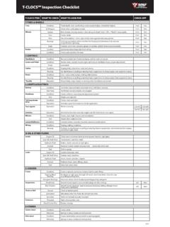
5 Hazardous environment, which may lead to personal injury or death, property damage, or economic loss. ATTENTION. Identifies information about practices or circumstances that can lead to personal injury ! or death, property damage, or economic loss. Identifies information that is critical for successful application and understanding of the IMPORTANT. product. Publication 1769-IN064A-EN-P - April 2003. Compact 16-point 24V dc Sink/Source High-speed Input Module 3. Module Description Item Description 1 bus lever (with locking function).
6 1 2a 2a upper panel mounting tab 2b lower panel mounting tab 3. 3 I/O diagnostic LEDs DANGER. Do Not Remove RTB Under Power Unless Area is Non-Hazardous 4 module door with terminal 10a IN 1. IN 0. identification label IN 2. IN 3. IN 4. IN 5. IN 7. IN 6 5a movable bus connector DC. 10 IN 9. COM1. IN 8. with female pins IN 11. IN 10. IN 13. IN 15. IN 12 5b stationary bus connector 10b DC. COM 2. IN 14. with male pins Ensure Adjacent Bus lever is Unlatched/Latched Before/After Removing/Inserting Module 4.
7 1769-IQ16F. 1769-IQ16. 6 nameplate label 8a 7a upper 2b tongue-and-groove slots 7a 7a 7b lower tongue-and-groove slots 8a upper DIN rail latch 5a 8b lower DIN rail latch 9 5b 9 write-on label (user ID tag). 10 removable terminal block (RTB). with finger-safe cover 10a RTB upper retaining screw 6 10b RTB lower retaining screw 7b 7b 8b Publication 1769-IN064A-EN-P - April 2003. 4 Compact 16-point 24V dc Sink/Source High-speed Input Module Module Installation Compact I/O is suitable for use in an industrial environment when installed in accordance with these instructions.
8 Specifically, this equipment is intended for use in clean, dry environments (Pollution degree 2(1)) and to circuits not exceeding Over Voltage Category II(2) (IEC 60664-1).(3). Prevent Electrostatic Discharge ATTENTION Electrostatic discharge can damage integrated circuits or semiconductors if you touch bus connector pins. Follow these guidelines when you handle the module: ! .. Touch a grounded object to discharge static potential. Wear an approved wrist-strap grounding device. Do not touch the bus connector or connector pins.
9 Do not touch circuit components inside the module. If available, use a static-safe work station. When not in use, keep the module in its static-shield box. Remove Power Remove power before removing or inserting this module. ATTENTION. When you remove or insert a module with power applied, an electrical arc may occur. An electrical arc can cause personal ! injury or property damage by: sending an erroneous signal to your system's field devices, causing unintended machine motion causing an explosion in a hazardous environment Electrical arcing causes excessive wear to contacts on both the module and its mating connector.
10 Worn contacts may create electrical resistance. (1). Pollution Degree 2 is an environment where, normally, only non-conductive pollution occurs except that occasionally a temporary conductivity caused by condensation shall be expected. (2). Over Voltage Category II is the load level section of the electrical distribution system. At this level transient voltages are controlled and do not exceed the impulse voltage capability of the product's insulation. (3). Pollution Degree 2 and Over Voltage Category II are International Electrotechnical Commission (IEC) designations.