Transcription of Comparative Analysis of Transformer and …
1 International Journal of Modern Engineering Research (IJMER) , , Jan-Feb. 2013 pp-551-563 ISSN: 2249-6645 251 | Page , 1 , 2 Nwachukwu3 1, 2, 3 Electrical and Electronics Engineering Department, university of Port Harcourt, River State Abstract: Electronics circuitry needs DC power source of a specific value to work effectively. This paper considers the design and evaluation of Transformer -based and Transformer less-based variable regulated DC power supply with the aim of presenting a Comparative Analysis between them; and their respective areas of applications. The quality, cost, size, weight, performance and efficient production of DC power supply thus pose a great deal of concern and attention in the DC power production of any electronic device. The design methodology used in this work involves Software design for component selection, improved hardware design, computer simulation and evaluation of transformation, rectification, filtration and regulation stages for both Transformer -based and Transformer less -based adjustable DC power supply with graphical outputs.
2 The results obtained after following the design specification was very satisfactory. The Transformer -based has a robust output current and well isolated from the supply voltage, which makes it more suitable for high current application, highly reliable for powering electronics devices while the Transformer less based DC source has smaller size, weight and cheaper so as to miniaturize electronics devices but limited to low current devices . It also generates far less noise, heat, input harmonic distortion levels, and higher transient response but lack of proper isolation unlike its counterpart thus result in lower Mean Time To Failure (MTTF). Transformer less variable DC power supply should be considered a viable option for lower power, small and low current applications where achieving the highest availability is not the top concern and cost, size and weight restrictions inhibit the use of traditional Transformer -based DC power supply.
3 Keywords: Transformer , Transformer -less, voltage regulator, simulation, variable DC power supply. I. Introduction In electrical and telecommunication engineering field, systems and equipments like amplifiers, satellites, microwave link systems to name but a few depend upon the availability of a stable and quality well regulated Direct Current (DC) power supplies for their correct operations. No electronics laboratory or technology is complete without a well regulated (or variable) DC power supply. It is the first essential element required in any electronics device. The construction, design and evaluation of this piece of electronic equipment- will find use both now and in future. The main and basic requirements of a well regulated DC power supply unit are Isolation between source and load, Low ripple, Low output impedance, Power factor, High transient response, Low levels of input harmonic distortion , Reduced power losses ,Good regulations, Strict output short-circuits protection, Workable size and weight.
4 II. Related Works In the work published by Mike Papadimitriou (----), LM317 was used for varying DC power supply. It is an adjustable 3 terminal positive voltage regulator capable of supplying in excess of over an output voltage range of V to 37 V. This voltage regulator is exceptionally easy to use and requires only two external resistors and capacitor to set the output voltage. In a similar work by National Microchip co-operation (-----) on Transformer -less Power Supplies, resistor was used as the transformation device and a reliable circuit diagram was given that works fine in computer simulation but the circuit offered no protection against over-current and over voltage issue. Williams, (1995) on Design and Construction of a Regulated Power Supply Unit used LM 78 XX device like the later. The voltage regulator is exceptionally easy to use and employs internal current limiting but capable of supplying in excess of over an output voltage range of V to 21 V and lacks internal thermal shutdown capability.
5 Ron J (2002) in his work, dealt with Transformer -less power supply using X-rated capacitor for low current applications of 100mA current ratings and a voltage of 12V. It was effective but the main disadvantage was that, it offered no isolation from the supply voltage and presents more of a safety issue. In the work published by Kiran Shrestha (Nov 2004) on Transformer less 12V Dual Power Supply. In this work two voltage output was achieved +12V and -12V using zener diode. This was proved and tested but still lacks protection against over-current and over voltage. In a similar work, Garage (2006) designed a variable DC power supply using LM 78XX. All the stages were effectively considered except the protection stage. In work published by Mohamkumar (2006) on Transformer less power supply, x-rated capacitor was used as transformation device instead of the Transformer ; and proved the effectiveness and efficiency of the x-rated capacitor and gave a well detailed circuit diagram of a fixed DC power supply using zener diode In the work published by Shamsul and Bin (Nov 2010) on Development of DC Power supply using power electronics applications, a fixed DC power supply was developed, simulated and proved to have worked effectively but the Comparative Analysis of Transformer and Transformer Less-Based Variable DC Power Supply International Journal of Modern Engineering Research (IJMER) , , Jan-Feb.
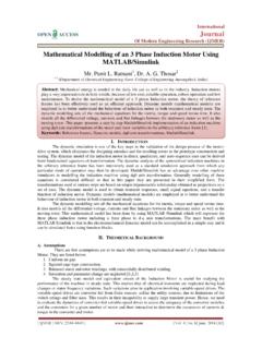
6 2013 pp-551-563 ISSN: 2249-6645 252 | Page input supply voltage lacks protection circuit, the output of the Transformer lacked noise suppression capacitor and the LM 317 T was not protected. Emerson Network Power (2012) contained vital information on comparing Transformer based and Transformer less uninterruptible power supplies. In this work emphasis were made on the uniqueness, differences and similarities between Transformer and Transformer -less based devices. III. Design Methodology The design methodology of both the Transformer and Transformer less based system involves five stages as shown in and A. The protection stage provides reliable and economical protection against high voltage transients, surges and over-current which may be produced. It comprises of fuse and varistor. In this work, the maximum current is 4A for the Transformer -based and 1A for the Transformer less type thus stating the rating of the fuse to be used in each of them.
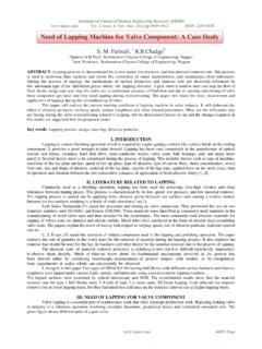
7 Since the main supply voltage is approximately 230, the voltage rating of the varistor used 250 Vac; the protection circuit is as shown below: : Protection circuit from the mains International Journal of Modern Engineering Research (IJMER) , , Jan-Feb. 2013 pp-551-563 ISSN: 2249-6645 253 | Page Transformation stage is used to transform the incoming line voltage of 230 down to a required voltage value for the power supply unit. For the two types of power supply that is the Transformer less and the Transformer based power supply, x-rated capacitor and step-down Transformer are used respectively. Step-down Transformer : The simulation waveform circuit Analysis shown below involves both the protection and the transformation stage using Transformer as the transformation device. Fig. 4: waveform Analysis of both protection and transformation stage for Transformer based DC power supply Using this formula Where: =primary (input) voltage,=number of turns on the primary coil, =secondary (output) voltage = number of turns on the primary coil.
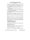
8 To produce a desired output voltage of 24 Vdc, a turn ratio of 10:1 Transformer was chosen, thus. X-rated AC capacitor: The simulation waveform circuit Analysis shown below involves both the protection and the transformation stage using Transformer as the transformation device. Graph 1 Graph 2 International Journal of Modern Engineering Research (IJMER) , , Jan-Feb. 2013 pp-551-563 ISSN: 2249-6645 254 | Page Figure 5: waveform Analysis of both protection and transformation stage for Transformer less based DC power supply The reactance () of the capacitor (C) in the mains frequency (f) can be calculated using the formula: From the formula above, if an X-rated capacitor of is used as shown in figure 15, the reactance ( will be as shown: The current that would be produced from a X-rated capacitor with an ac source of 230 can begotten using the ohmic equation.)
9 This value is the ideal current value, but the actual current from a X-rated capacitor with an ac source of 230 is 100 cited from Table 2 . Practically a single X-rated capacitor could give a current, therefore, three of the X-rated capacitor connected in parallel with each other would give a current of 300 ( three times), this current rating is well over sufficient for all low current devices. Rectification stage is the stage after transformation stage that aids in the conversion of AC to DC signal. In this work a full wave rectification is used, because of its fundamental advantages over the half wave rectifier counterpart. Bridge rectifier is used rather its counterpart because it does not require a special centre tapped Transformer , thereby reducing its size and cost. The bridge rectifier consists of 4 IN4001 silicon diodes. Livewire simulation of both the transformation and rectification stage for the Transformer based and Transformer less based Dc power supply are as shown below.
10 Graph 1 Graph 2 International Journal of Modern Engineering Research (IJMER) , , Jan-Feb. 2013 pp-551-563 ISSN: 2249-6645 255 | Page Fig. 6: waveform Analysis of transformation and rectification stage for the Transformer based circuit Figure 7: waveform Analysis of transformation and rectification stage for the Transformer less based circuit From the figures 6 and 7 above the following mathematical expressions can be deduced. Output AC signal from transformation stage Peak to Peak AC signal from transformation stage When passed through a bridge rectifier, the DC output signal is given by: DC output signal DC output signal Note that in a full wave bridge rectifier only 2 of the 4 diodes works simultaneously at any given time. Each of the diodes has a voltage drop ranging from to V. Graph 1 Graph 2 Graph 2 Graph 1 International Journal of Modern Engineering Research (IJMER) , , Jan-Feb.