Transcription of Comparison of tripping characteristics for miniature ...
1 Comparison of tripping characteristics for miniature circuit -breakersThe requirements for Protection for safety Protection against overcurrent are specified in IEC 60364-4-43. miniature circuit -breakers are used to protect cables in installations. They should disconnect automatically as soon as the combination of the current rise and duration causes the cable or a component to heat up circuit -breaker are used for: overload protection and short circuit protectionin electrical circuits as well as protection against electric shock by automatic disconnection is performed by two different releases. The instantaneous tripping by electro-magnetic release provides protection against short circuits.
2 This is only depen-dent on current. The thermal bi-metal release is used for pro-tection against overload. It trips by temperature rise, in other words both current and time. When selecting miniature circuit -breakers for short - circuit protection in accordance with IEC 60364-4-43, the permis-sible let-through value I2 x t for extremely short disconnection times (< ) is contrasted with the Joulean heat impulse of the current k2 x S2 of the cable in order to verify whether sufficient protection is guaranteed in the event of a short circuit . The combination of tripping curves of the electro-magnetic release and the thermal bi-metal release result in an overall tripping curve for overload protection.
3 This curve referred to the individual tripping characteristic represents the time/current behavior of a miniature desire for the best protection, which requires miniature circuit -breakers to be highly sensitive, has to be reconciled with the different operating characteristics of the loads to be protected. Load current peaks must be permitted to pass unhindered, yet at the same time a disconnection must be ensured in the event of relatively low, but continuous, over-loads. Various tripping characteristics are therefore available for circuit -breakers depending on the type of component or equipment to be protected: B, C and D for overcurrent protection of cables in accordance with IEC/EN 60898-1 K for the protecting motors and transformers and simultaneous overcurrent protection of cables with overload tripping based on IEC/EN 60947-2 Z for control circuits with high impedances.
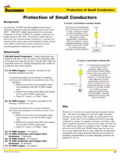
4 Voltage converter circuits and semicable protection and simultaneous overcurrent protection of cables with overload tripping based on IEC/EN 60947-2 Vielfaches des Grenzkennlinie aus dem1 kalten = x InI1 = x InR= 30 C30JI1I2 JRI1 I2 I1 = x ln I2 = x ln JR = 30 CTripping timeSecondsMinutesMultiple of the rated currentTripping curve from cold state2 2 CDC400002D0201 Prospective short - circuit current IK/A gL fuse circuit -breakerLet-through I2t / A2sFig. 2 Load limit curve for PVC-insulated cables1234 Area of complete heat dissipation with conti-nuous current Iz Permissible operating temperature 70 C (PVC)Area of limited heat dissipation in the event of overload I2 x IzArea without heat dissipation for a maximum short circuit duration of 5s I2t = constant, permissible short circuit temperature 160 CWith a disconnection time of < , the I2t of the miniature circuit -breaker must be less than k2 S2 of the cable (k = material value in accordance with IEC /HD 60364-4-43.)
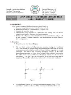
5 S = cable cross section in mm2)Iz1,45 Iz10 Iz100 IzIzIk = Materialwert nach DIN VDE 0100 Teil 540S = Leiterquerschnitt in mm2 Bei Ausschaltzeit < 0,1s mu I2tdes Sicherungsautomaten kleinersein als k2 S2 der LeitungBereich ohne W rmeableitungbei max. Kurzschlu dauer 5s;I2t = konstantzul. Kurzschlu temperatur 160 CBereich begrenzter W rme-ableitung bei berlastI2 1,45 x Iz0,1 s5 s1 ht20 JahreBereich vollkommener W rme-ableitung bei Dauerstrom Izzul. Betriebstemperatur 70 CIz Iz 10 Iz 100 IzIIz20years1 h5 sect2134Cu cable, permitted I2t valuesA2s82,60029,70013,2007,400 Fig. 1 energy I2tProtection against short -circuitsFigure 1 shows typical let-through or I2t values of overcurrent circuit -breakers.
6 In the case of S201-B16 miniature circuit -breaker, this causes the let-through energy to be limited to approx. 20,000 A2s if a prospective short - circuit current iK = 6 kA occurs. This value is far less than 29,700 A2, meaning PVC-insulated Cu cables with a cross-section of mm2 can be protected in the event of a protection in accordance with IEC 60364-4-43 For protection against overload, the protective device must be selected based on the current carrying capacity Iz of the cable:Ib In Iz (1)I2 x Iz (2)Ib = Design current of a circuitIn = Rated current of the protective deviceIz = Current carrying capacity of the cable in accordance with IEC/HD 60364-5-52I2 = Current ensuring effective operation in the conventional time of the protective device50, 63 A32, 40 A20, 25 A16 A10, 13 A6 AB.
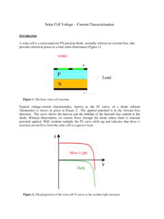
7 CIn =102 6 8 103 2 3 4 610586432104864321032 CDC400002D0201 3 Service life of PVC-insulated cables according to the Arrhenius equation Cable temperature Service life 70 C years 90 C years 100 C yearIEC 60364-4-43In individual cases, conditions (1) and (2) may not guarantee complete protection in accordance with the rules as aforesaid may not assure protection in certain cases, for example where sustained overcurrents less than I2 occur. In such cases, consideration should be given to selecting a cable with a larger cross-section general aim is to use the selected characteristic to protect a cable in accordance with its load capacity limit as shown in figure against overloadFurthermore, protection devices with I2 values close to the rated current In can increase the effectiveness of overload protection significantly.
8 Please refer in these cases to K- or Z-characteristic with I2 = 1,2 x des = x InI1 = x In= 20 C= Grenzkennlinie aus dem1 kalten ZustandCKZ11I2 = x InI1 = x In= 30 of PVC-insulated cables at overload Load Cable temperature* x In 70 C x In 86 C x In 116 C* 90 % of the temperature value is reached from operating temperature after 5 of the rated currentTripping timeSecondsMinutesI1 = x ln I2 = x ln JR = 20 C (K, Z) I1 = x ln I2 = x ln JR = 30 C (B, C, D) tripping curve from cold state4 2 CDC400002D0201 Comparison of tripping characteristics Z and B 24 V DC control circuitsIn order to achieve the best possible protection of sensitive devices, such as contacts or prefabricated cables of sensors/limit switches, the instantane-ous tripping must clear even low short - circuit currents within maximum cable lengths in relation to loop resistance must not be ex-ceeded.
9 Taking account of various parameters, the maximum cable lengths could be as mm2, two-wire, Cu: MCB B6 max. 10 m MCB Z2 max. 47 m MCB Z6 max. 18 mDue to the low instantaneous tripping current, the maximum cable lengths can be realized by using the Z direct current, the tripping values of the electromagnetic releases are increased by a factor of against overloadAs stated before it is obvious that tripping characteristic Z provides better protection during operation and is easier to choose when des = x InI1 = x In= 20 C= Grenzkennlinie aus dem1 kalten ZustandZ1I2 = x InI1 = x In= 30 C51 RJRJJRJRT emperature of PVC-insulated cables at overload Load Cable temperature* x In 70 C x In 86 C x In 116 CService life of PVC-insulated cables using the Arrhenius equation Cable temperature Service life 70 C
10 Years 90 C years 100 C year* 90 % of the temperature value is reached from operating temperature after 5 of the rated currentTripping timeSecondsMinutesI1 = x ln I2 = x ln JR = 20 C (Z) I1 = x ln I2 = x ln JR = 30 C (B) tripping curve from cold state2 CDC400002D0201 5 Comparison of tripping characteristics C and K K solves the conflict of service conti-nuity in the event of peak currents and rapid disconnection in the event of a circuits where inrush currents or starting current peaks can occur due to motors, chargers, welding trans-formers, etc.