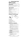
Transcription of Components of the Brake Control D E A. A B B. C. D. E.
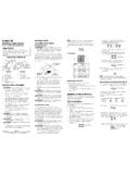
1 Electronic Brake ControlFor 2, 4, 6* and 8* Brake applicationsComponents of the Brake Slide Mounting KnobImportant Facts to not mount or activate RF generating items (cellphones, two way radios) near (less than 12") theBrake Reversing the connection to a break-away battery on the trailer will destroy the Brake Disconnect trailer plug from the towvehicle prior to testing a breakaway switch or youmay destroy the Brake light is: GREEN when trailer is connected. RED when Brake pedal or manual is activated and trailer is GREEN light draws 5 milliamperes of current from tow vehicle. It would take over 10,000hours to drain the tow vehicle The level adjustment is level adjustment determines whether automaticbraking response is delayed or Brake Control is activated by inertia. It senses deceleration and generates an output that reflects the inertia sensed. In a stationarystate, the Brake Control will not apply the trailer brakes unless the Manual Slide Knob is The Gross Combined Weight Rating (GCWR) must never exceed the vehiclemanufacturers This Control specfically designed for use with electric trailer Technical Assistance and Warranty Informationcall: 1-888-785-5832 or GuideWARNING The Brake Control must be mount-ed from -20 degrees nose down to 70 degrees noseup.
2 (See Below.) Failure to install Brake controlwithin these constraints may cause your Control to become Bracket BracketB.#6 x 3/8 Screws Drilling or use of longer screws may damage mount bracket to a solid supplied #6 x 3/8 screws on each sideinto the mounting Control to desired position and tightenscrews until THIS FIRST:Read and follow all instructions carefully before installing or operating the Brake Control . Keepthese instructions with the Brake Control forfuture of TravelDirection of TravelCorrectIncorrectDEBA-20 0 70 ABCP/N 3840 REV J08/03 Leveling the SensorAfter the Brake Control has been securely mountedthe level adjustment must be trailer to tow vehicle, Bi-ColoredLight should glow power knob to maximum by fully rotating tow vehicle s Brake pedal and hold. the Level Knob counter-clockwise(towards the back of the Control ) until the Bi-Colored Light starts to change colors from GREEN to rotate the Level Knob clockwise(towards the front of the Control ) until a shade of ORANGE is Light should show: DIM ORANGE for a typical setting.
3 BRIGHT ORANGE for an aggressive setting. DIM RED for a more aggressive Brake the Power to the Trailer BrakesOnce the Control has been installed and properlyleveled, it is necessary to set the power needed to stop the trailer during a braking trailer to tow Power Knob to the 12 o clock tow vehicle and trailer on a dry levelpaved surface at 25 mph and apply manualslide : Range of adjustment for the level knobfrom DIM ORANGE to DIM RED is 20 degrees of rotation. If trailer brakes lock up: Turn power down using power knob.(Rotate power knob toward the 8 o clock position, counter-clockwise.) If braking was not sufficient: Turn power up using power knob. (Rotatepower knob toward the 5 o clock position,clockwise.) Step (3) until power has been set to a point just below wheel lock up or at a sufficient force as to achieve maximumbraking the Brake pedal, make a few low speedstops to check the Power and Level adjust-ments. The automatic response ( Brake pedal)is initiated and terminated via the stoplightswitch.
4 When the Brake pedal is released,trailer braking will TuningNow that the Power has been set, it is time to finetune the level setting for the majority of the stopping that you will be several slow (25 MPH) stops as if coming up to a stop sign and take notice of how the trailer brakes respond: Brakes Grab Too Much You have an Aggressive Setting:To correct this condition rotate level knobclockwise, toward you, see below. Trailer Tending to Push Tow Vehicle You have a Delayed Setting:To correct this condition rotate level knobcounter-clockwise, away from you, see until desired trailer braking is :When the Brake Control is leveled properly there will be very little current flowingthrough the Brake magnets in a static state withthe foot pedal depressed. The Brake magnets willhum when there is current flowing through the Bi-Colored Light shows any colorother than GREEN, there is current flowingthrough the Brake :1. Front of the Voyager must be horizontal,see The Voyager must be parallel to direction of travel,see This Brake Control is activatedby inertia and requires the level to be setproperly, or the braking response will be tooharsh or properly level the sensor, the trailer andtow vehicle must be parked on a level surfaceand trailer must be connected to tow : warm the trailer's brakes before setting the power.
5 Warm trailer brakes tendto be more responsive than cold brakes. Towarm trailer brakes, drive a short distance(1/4 mile) at 45 MPH with manual leverengaged enough to cause trailer braking at a low The power should never be sethigh enough to cause trailer brakes to lockup. Skidding trailer wheels can cause loss ofdirectional stability of trailer and tow vehicle. power may need to be adjusted for different load weights and road all trailer brakes will lock up due to various conditions. However, inability tolock up the brakes generally indicates theneed for an inspection to determine the the power is set correctly you shouldfeel unified braking between the trailer andtow in doubt of the proper setting procedures review the above steps starting at LEVELING THE SENSOR through FINETUNING or consult your tow card includedwith your Brake lectronique de freinPour applications de 2, 4, 6* et 8* freins Composants de la commande de de glissi re de montage de moin lumineux deux de niveauFaits importants garder en m pas monter ni actionner des appareils produisant des HF (t l phones cellulaires,radios bidirectionnelles) proximit (moins de 12po) de la commande de L inversion de la connexion unebatterie de d rive sur la remorque d truira la commande de D brancher la fiche de remorquedu v hicule de remorquage avant de faire l essaid un interrupteur de d rive, sinon on risque de d truire la commande de t moin lumineux est.
6 VERT lorsque la remorque est raccord e. ROUGE lorsque la p dale de frein ou le bouton manuel est actionn et que la remorqueest raccord t moin lumineux VERT consomme 10 milli-amp res de courant du v hicule de remorquage. Il faudrait plus de 5000 heures pour puiser labatterie du v hicule de Le r glage du niveau estCRITIQUE. Le r glage du niveau d termine si la r ponse automatique de freinage est retard e ou commande de frein est actionn e par l iner-tie. Elle d tecte la d c l ration et produit une sor-tie qui refl te l inertie d tect e. l tat fixe, lacommande de frein ne serrera pas les freins de laremorque moins que le bouton glissi remanuelle ne soit actionn .SituationProbable CauseTow vehicle connected to trailer,NO GREEN Corrosion on trailer plug Loose POWER or GROUND vehicle connected to trailer, light is Manual Slide Knob is activated:A. No RED Light is dim RED or flashing Light glows dim RED and gets brighter as POWER Knob is POWER set at or near Short on Brake line (BLUE wire).
7 3. BLACK & WHITE wires reversed, 12 volts from external source on Brake line (BLUE wire).1. Open on GROUND line (WHITE wire).2. Short on Brake line (BLUE wire).1. Short on Brake line (BLUE wire).2. Defective Brake with foot pedal is too Sensor set too aggressive, see LEVELING Power set too is delayed for extended Sensor set improperly, see LEVELING Power set too vehicle connected to trailer, Brake pedal depressed:A. No RED Vehicle not moving, need to be moving for brakes to No signal from Brake light, test voltage on RED Sensor set improperly, see LEVELING Bad connection on RED Blown stoplight A: Trailer Brake Adjustment**Brakes should be adjusted after the first 200 miles of operation when the Brake shoes and drums have seated and at 3000 mile intervals, or as use and performance brakes should be adjusted in the following up trailer and secure on adequate capacity jackstands. Follow trailer manufacturers recommendations forlifting and supporting the unit.
8 Check that the wheel anddrum rotate not lift or support trailer on any part ofthe axle or the suspension the adjusting hole cover from the adjusting sloton the bottom of the Brake backing a screwdriver or standard adjusting tool, rotate thestarwheel of the adjuster assembly to expand the brakeshoes. Adjust the Brake shoes out until the pressure of the linings against the drum makes the wheel very difficult to : With drop spindle axles, a modified adjusting tool with about an 80 degree angle should be rotate the starwheel in the opposite direction untilthe wheel turns freely with a slight lining the adjusting hole cover and lower the wheel to the the above procedure on all crawl under your trailer unless it isresting on properly placed jack the trailer manufacturers recommendations for liftingand supporting the unit. Do not lift or place supports on anypart of the suspension system.**Note: Trailer Brake Adjustment procedures courtesy Dexter CECI EN PREMIER :Il convient de lire et de suivre attentivementtoutes les consignes avant de poser ou d utiliserla commande de frein.
9 Ces consignes doivent tre conserv es avec la commande de frein pourconsultation ChartMise du capteur niveauUne fois la commande de frein mont e solidement,il doit y avoir mise la remorque au v hicule deremorquage, le t moin lumineux deux couleurs doit tre le bouton de puissance au maximum en tournant compl tement en sens et tenir la p dale de frein du v hicule de remorquage. le bouton de niveau en sens anti-horaire(vers l arri re de la commande) jusqu ce que le t moin lumineux deux couleurs commence passer du VERT au soigneusement le bouton de niveau ensens horaire (vers l avant de la commande)jusqu ce qu une teinte d ORANGE soit t moin lumineux deux couleurs doit montrer : Un ORANGE P LE pour un r glage type. Un ORANGE VIF pour un r glage agressif. Un ROUGE P LE pour un r glage plus Cette commande de frein est actionn e par l inertie et n cessite que le niveau soit r gl ad quatement, sinon la r ponse de freinage sera trop dure ou r gler ad quatement le niveau du capteur,la remorque et le v hicule de remorquagedoivent tre gar s sur une surface niveau et la remorque doit tre raccord e au v hiculede Le poids technique max-imal combin (Gross Combined Weight Rating GCWR) ne doit jamais d passer les recommandations du fabricant du v commande est con ue por tre utilis eavec des freins de remorque assistance technique et informations concernant la garantie, pri re d appeler le :1-888-785-5832 ou d installationAVERTISSEMENT La commande de frein doit tre mont e depuis -20 degr s nez vers le bas jusqu 70 degr s nez vers le haut.
10 (Voir ci-apr s.) Le d fautde poser la commande de frein l int rieur de cescontraintes peut rendre la commande inop traditionnel du de No. 6 x 3/8 po Le per age ou l utilisation de vis plus longues peut endommager l unit . solidement le support sur une surface rer les vis No. 6 x 3/8 po fournies dans les trous de montage de chaque c t . gler la commande la position d sir e et ser-rer les vis fermement mais non 0 70 ABSens de marcheSens de cher la p dale de glage de la puissance aux freinsde la remorqueUne fois la commande pos e et mise niveauad quatement, il faut r gler la puissance n cessairepour arr ter la remorque lors d un v nement de la remorque au v hicule de le bouton de puissance la position 12 le v hicule de remorquage et laremorque sur une surface pav e, s che, niveau, 40 km/hre, et appliquer le bouton glissi re manuelle. Si les freins de la remorque se verrouillent : R duire la puissance l aide du bouton depuissance. (Tourner le bouton de puissancevers la position 8 heures, en sens anti-horaire.)