Transcription of Configuring GPIO Appendix on the STM32F4xx E
1 Configuring gpio on the STM32F4xxIntroductionConfiguring general purpose input/output ( gpio ) on the Cortex-M4 takes more effort than you might think. Fortunately a userfriendly library is available that makes this very easy to do. Onceagain thanks to Tilen Majerle, we have a nice :/** * gpio library for STM32F4xx devices * * @author Tilen Majerle * @email * * @link * @version * @ide Keil uVision * @licenseGNU GPL v3 Initialize gpio Pins In the STM32 the are five gpio banks GPIOA GPIOG When using the library there are four considerations: gpio ModeAppendixEAppendix E Configuring gpio on the STM32F4xxE 2 ECE 5655/4655 Real-Time DSP gpio Output Type gpio speed gpio pullup/pulldown resistors C typedef enumerations are used to create a convenient wayof setting the various attributesGPIO Mode TM_GPIO_Mode_IN.
2 Set pin as input TM_GPIO_Mode_OUT: Set pin as output TM_GPIO_Mode_AF: Set pin as alternate function TM_GPIO_Mode_AN: Set pin as analogGPIO Output Type TM_GPIO_OType_PP: gpio pin is push-pull TM_GPIO_OType_OD: gpio pin is open-drainGPIO Speed TM_GPIO_Speed_Low: speed register set to 0x00 TM_GPIO_Speed_Medium: speed register set to 0x01 TM_GPIO_Speed_Fast: speed register set to 0x02 TM_GPIO_Speed_High: speed register set to 0x03 gpio Pullup/Pulldown TM_GPIO_PuPd_NOPULL: NonePin Read Write FunctionsECE 5655/4655 Real-Time DSPE 3 TM_GPIO_PuPd_UP: Pull up TM_GPIO_PuPd_DOWN: Pull downPin Read Write Functions The library supplies the following functions/macros for read-ing and writing pin values: TM_GPIO_SetPinLow(GPIOx, GPIO_Pin) TM_GPIO_SetPinHigh(GPIOx, GPIO_Pin) TM_GPIO_SetPinValue(GPIOx, GPIO_Pin, val) TM_GPIO_TogglePinValue(GPIOx, GPIO_Pin) TM_GPIO_SetPortValue(GPIOx, value): TM_GPIO_GetInputPinValue(GPIOx, GPIO_Pin): TM_GPIO_GetOutputPinValue(GPIOx, GPIO_Pin): The library defines all of these functions as macros for speedreasons For more details see : PN & PN Sync To Output PortsAs a simple example we consider a PN sequence generator beingoutput from a look-up table (LUT) along with a sync signal.
3 Allof this is inside an ISR, with upsampling, to make the bit periodan integer multiple of the sampling clock. The main module code listing is given below: Appendix E Configuring gpio on the STM32F4xxE 4 ECE 5655/4655 Real-Time DSP// #include " "#include " "#include " "#include " "#include " "#define CODE_PERIOD 31#define L_UP 4int16_t PN_tbl[CODE_PERIOD] = {1, 1, 1, 1, 1, 0, 0, 0, 1, 1, 0, 1, 1, 1, 0, 1, 0, 1, 0, 0, 0, 0, 1, 0, 0, 1, 0, 1, 1, 0, 0};int16_t PN_sync_tbl[CODE_PERIOD] = {0, 0, 0, 0, 1, 0, 0, 0, 0, 0, 0, 0, 0, 0, 0, 0, 0, 0, 0, 0, 0, 0, 0, 0, 0, 0, 0, 0, 0, 0, 0};static int16_t idx_PN = 0;static int16_t idx_up = 0.
4 Void SPI2_IRQH andler(){ int16_t left_out_sample = 0; int16_t right_out_sample = 0; int16_t left_in_sample = 0; int16_t right_in_sample = 0; if (SPI_I2S_GetFlagStatus(I2Sx, I2S_FLAG_CHSIDE) == SET) { left_in_sample = SPI_I2S_ReceiveData(I2Sx);if (idx_up == 0) //Do once per upsample period{ //write to gpio pins with desired logic value TM_GPIO_SetPinValue(GPIOC, GPIO_Pin_8, PN_tbl[idx_PN]); TM_GPIO_SetPinValue(GPIOC, GPIO_Pin_9, PN_sync_tbl[idx_PN]); idx_PN = (idx_PN+1) % CODE_PERIOD;//increment PN LUT index}idx_up = (idx_up+1) % L_UP; while (SPI_I2S_GetFlagStatus(I2 Sxext, SPI_I2S_FLAG_TXE ) != SET){} SPI_I2S_SendData(I2 Sxext, left_out_sample); } else { right_in_sample = SPI_I2S_ReceiveData(I2Sx); right_out_sample = 0; while (SPI_I2S_GetFlagStatus(I2 Sxext, SPI_I2S_FLAG_TXE ) !)}}
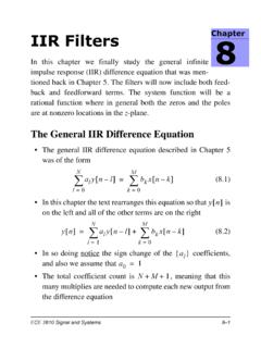
5 = SET){} SPI_I2S_SendData(I2 Sxext, right_out_sample); }}Example: PN & PN Sync To Output PortsECE 5655/4655 Real-Time DSPE 5int main(void){ /* Init pins PC8, 9 for output, no pull-up, and high speed*/ TM_GPIO_Init(GPIOC, GPIO_Pin_8 | GPIO_Pin_9, TM_GPIO_Mode_OUT, TM_GPIO_OType_PP, TM_GPIO_PuPd_NOPULL, TM_GPIO_Speed_High);stm32_wm5102_init(FS _48000_HZ, WM5102_LINE_IN, IO_METHOD_INTR); while(1){}} In main we see that GPIOC pins 8 and 9 are set for output On the Discovery these are pins labeled PC8 and PC9respectively The output type is push-pull There are no resistors for pullup or pulldown The speed is high We now build and run this code, and then take at the outputpins using the Analog Discovery logic analyzerAppendix E Configuring gpio on the STM32F4xxE 6 ECE 5655/4655 Real-Time DSP The results are shown below.
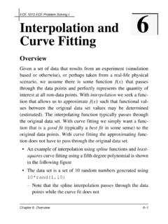
6 The waveforms are as expected for a PN31 sequence beingclocked 48/4 = 12 KHz Here the sample rate is 48 kHz and the upsample factor is 4 Observe the PN and PN sync channel outputsMeasure the PN sequence periodLabels matchDiscovery pinlabels; good!Measure the 5 Ones DurationPN31 Period5 Ones PeriodExample: PN & PN Sync To Output PortsECE 5655/4655 Real-Time DSPE 7 A PN31 code has period of 31 bits and is known to have onepattern of 5 ones Comparing the measured results with theory, we have PN period = ms vs ms 5 Ones period = vs s Similar resuts are obtained with the Saleae Logic 8 Pro1: Measured PN period = ms (A1/A2 marker pair) Measured 5 ones period = ms (B1/B2 marker pair)1.
7 10 31 10 5 s=Top two traces the digital capture at Ms/sBottom two traces the analog capture at Ms/sAppendix E Configuring gpio on the STM32F4xxE 8 ECE 5655/4655 Real-Time DSP