Transcription of Configuring VRF-lite - Cisco
1 CHAPTER27-1 Software Configuration Guide Release (31)SGOL-8881-0127 Configuring VRF-liteVirtual Private Networks (VPNs) provide a secure way for customers to share bandwidth over an ISP backbone network. A VPN is a collection of sites sharing a common routing table. A customer site is connected to the service provider network by one or more interfaces, and the service provider associates each interface with a VPN routing table. A VPN routing table is called a VPN routing /forwarding (VRF) table. With the VRF-lite feature, the Catalyst 4500 series switch supports multiple VPN routing /forwarding instances in customer edge devices. ( VRF-lite is also termed multi-VRF CE, or multi-VRF Customer Edge Device). VRF-lite allows a service provider to support two or more VPNs with overlapping IP addresses using one chapter includes these topics: Understanding VRF-lite , page 27-2 Default VRF-lite Configuration, page 27-3 VRF-lite Configuration Guidelines, page 27-4 Configuring VRFs, page 27-5 Configuring a VPN routing Session, page 27-5 Configuring BGP PE to CE routing Sessions, page 27-6 VRF-lite Configuration Example, page 27-7 Displaying VRF-lite Status, page 27-11 NoteThe switch does not use Multiprotocol Label Switching (MPLS) to support VPNs.
2 For information about MPLS VRF, refer to the Cisco IOS Switching Services Configuration Guide NoteFor complete syntax and usage information for the switch commands used in this chapter, see the Cisco Catalyst 4500 Series Switch Command Reference and related publications at this location: the command is not found in the Cisco Catalyst 4500 Command Reference, you can locate it in the larger Cisco IOS library. Refer to the Catalyst 4500 Series Switch Cisco IOS Command Reference and 27-2 Software Configuration Guide Release (31)SGOL-8881-01 Chapter 27 Configuring VRF-liteUnderstanding VRF-literelated publications at this location: VRF-liteVRF-lite is a feature that enables a service provider to support two or more VPNs, where IP addresses can be overlapped among the VPNs. VRF-lite uses input interfaces to distinguish routes for different VPNs and forms virtual packet-forwarding tables by associating one or more Layer 3 interfaces with each VRF.
3 Interfaces in a VRF can be either physical, such as Ethernet ports, or logical, such as VLAN SVIs, but a Layer 3 interface cannot belong to more than one VRF at any support on Cat 4500 does not include the Provider Edge MPLS funcitonality. More specifically, MPLS label switching and MPLS control plane are not supported in the VRF-lite interfaces must be Layer 3 includes these devices: Customer edge (CE) devices provide customer access to the service provider network over a data link to one or more provider edge routers. The CE device advertises the site s local routes to the provider edge router and learns the remote VPN routes from it. A Catalyst 4500 series switch can be a CE. Provider edge (PE) routers exchange routing information with CE devices by using static routing or a routing protocol such as BGP, RIPv1, or RIPv2.
4 The PE is only required to maintain VPN routes for those VPNs to which it is directly attached, eliminating the need for the PE to maintain all of the service provider VPN routes. Each PE router maintains a VRF for each of its directly connected sites. Multiple interfaces on a PE router can be associated with a single VRF if all of these sites participate in the same VPN. Each VPN is mapped to a specified VRF. After learning local VPN routes from CEs, a PE router exchanges VPN routing information with other PE routers by using internal BGP (IBPG). Provider routers (or core routers) are any routers in the service provider network that do not attach to CE devices. With VRF-lite , multiple customers can share one CE, and only one physical link is used between the CE and the PE. The shared CE maintains separate VRF tables for each customer and switches or routes packets for each customer based on its own routing table.
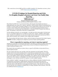
5 VRF-lite extends limited PE functionality to a CE device, giving it the ability to maintain separate VRF tables to extend the privacy and security of a VPN to the branch office. Figure 27-1 shows a configuration where each Catalyst 4500 series switch acts as multiple virtual CEs. Because VRF-lite is a Layer 3 feature, each interface in a VRF must be a Layer 3 interface. 27-3 Software Configuration Guide Release (31)SGOL-8881-01 Chapter 27 Configuring VRF-liteDefault VRF-lite ConfigurationFigure 27-1 Catalyst 4500 Series Switches Acting as Multiple Virtual CEsThis is the packet-forwarding process in a VRF-lite CE-enabled network as shown in Figure 27-1: When the CE receives a packet from a VPN, it looks up the routing table based on the input interface. When a route is found, the CE forwards the packet to the PE.
6 When the ingress PE receives a packet from the CE, it performs a VRF lookup. When a route is found, the router adds a corresponding MPLS label to the packet and sends it to the MPLS network. When an egress PE receives a packet from the network, it strips the label and uses the label to identify the correct VPN routing table. Then the egress PE performs the normal route lookup. When a route is found, it forwards the packet to the correct adjacency. When a CE receives a packet from an egress PE, it uses the input interface to look up the correct VPN routing table. If a route is found, the CE forwards the packet within the configure VRF, create a VRF table and specify the Layer 3 interface associated with the VRF. Then configure the routing protocols in the VPN and between the CE and the PE. BGP is the preferred routing protocol used to distribute VPN routing information across the provider s backbone.
7 The VRF-lite network has three major components: VPN route target communities Lists of all other members of a VPN community. You need to configure VPN route targets for each VPN community member. Multiprotocol BGP peering of VPN community PE routers Propagates VRF reachability information to all members of a VPN community. You need to configure BGP peering in all PE routers within a VPN community. VPN forwarding Transports all traffic between all VPN community members across a VPN service-provider VRF-lite ConfigurationTable 27-1 shows the default VRF 1 VPN 2 VPN 1 VPN 2 CEMPLS-VRFrouterMPLS-VRFrouterCatalyst 4500switchCatalyst 4500switchPEPEMPLS networkCECE = Customer edge devicePE = Provider edge router99721 SiSiTable 27-1 Default VRF ConfigurationFeatureDefault SettingVRFD isabled. No VRFs are import maps, export maps, or route maps are Configuration Guide Release (31)SGOL-8881-01 Chapter 27 Configuring VRF-liteVRF-lite Configuration GuidelinesVRF-lite Configuration GuidelinesConsider these points when Configuring VRF in your network: A switch with VRF-lite is shared by multiple customers, and all customers have their own routing tables.
8 Because customers use different VRF tables, the same IP addresses can be reused. Overlapped IP addresses are allowed in different VPNs. VRF-lite lets multiple customers share the same physical link between the PE and the CE. Trunk ports with multiple VLANs separate packets among customers. All customers have their own VLANs. VRF-lite does not support all MPLS-VRF functionality: label exchange, LDP adjacency, or labeled packets. For the PE router, there is no difference between using VRF-lite or using multiple CEs. In Figure 27-1, multiple virtual Layer 3 interfaces are connected to the VRF-lite device. The Catalyst 4500 series switch supports Configuring VRF by using physical ports, VLAN SVIs, or a combination of both. The SVIs can be connected through an access port or a trunk port. A customer can use multiple VLANs as long as they do not overlap with those of other customers.
9 A customer s VLANs are mapped to a specific routing table ID that is used to identify the appropriate routing tables stored on the switch. The Layer 3 TCAM resource is shared between all VRFs. To ensure that any one VRF has sufficient CAM space, use the maximum routes command. A Catalyst 4500 series switch using VRF can support one global network and up to 64 VRFs. The total number of routes supported is limited by the size of the TCAM. Most routing protocols (BGP, OSPF, EIGRP, RIP and static routing ) can be used between the CE and the PE. However, we recommend using external BGP (EBGP) for these reasons: BGP does not require multiple algorithms to communicate with multiple CEs. BGP is designed for passing routing information between systems run by different administrations. BGP makes it easy to pass attributes of the routes to the CE.
10 VRF-lite does not support IGRP and ISIS. VRF-lite does not affect the packet switching rate. Multicast cannot be configured on the same Layer 3 interface at the same time. The capability VRF-lite subcommand under router ospf should be used when Configuring OSPF as the routing protocol between the PE and the maximum tableThe default for an interface is the global routing 27-1 Default VRF Configuration (continued)FeatureDefault Setting27-5 Software Configuration Guide Release (31)SGOL-8881-01 Chapter 27 Configuring VRF-liteConfiguring VRFsConfiguring VRFsTo configure one or more VRFs, perform this task:NoteFor complete syntax and usage information for the commands, refer to the switch command reference for this release and the Cisco IOS Switching Services Command Reference for Release the no ip vrf vrf-name global configuration command to delete a VRF and to remove all interfaces from it.