Transcription of Contents
1 ContentsSection I 22 Grounding electrodes for buildings, industrial installations andsubstations 22 grounding 22 or rod grounding 22 or round conductor grounding 22 and types of grounding electrodes 22 Resistivity of soil (r) 22 Measuring the ground resistance 22 Metal for the grounding conductor 22 of the grounding conductor 22 Jointing of grounding conductors 22 Maintenance of grounding stations 22/806 Section II 22 Grounding practices in a power generating station 22 Tolerable potential difference at a location 22 Voltage gradients 22 step voltage (Es) 22 touch voltage (Et) 22 voltage or safe design voltage (Em) 22 potential rise (GPR) 22 voltage (Etr) 22 parameters 22 Determining the leakage current through a body 22 Body resistance 22 Ground resistance 22 Measuring the average resistivity of soil 22 Improving the performance of soil 22 Conductivity 22 Soil moisture and contact resistance 22 Determining the ground fault current 22 Designing a grounding grid 22 Minimum size of grid conductors 22 Corrosion factor 22 Maximum touch and step voltages of a grounding station 22 Estimating the value of ground conductor length (L)
2 22/816 Relevant Standards 22/821 List of formulae used 22/821 Further Reading 22/82222 Groundingpractices22/797 Grounding practices22/799 SECTION Grounding electrodes forbuildings, industrialinstallations and substationsThe following are a few types of grounding electrodescommonly used for the grounding of buildings, industrialinstallations, equipment grounding or small and medium-sized substations. Power generating stations and largeswitchyards may experience large ground fault currentsaccordingly, grounding electrodes demand a lot more safetyconsiderations and are discussed in Section Plate groundingRefer to Figure The approximate resistance to groundin a uniform soil can be expressed byRA = 4 2 rpW (derived from Equation ( )) ( )
3 Wherer = resistivity of soil, considered uniform in W = area of each side of the plate in minimum thickness of plate is recommended as For cast iron mm For GI or steel mm For copper mmand size not less than 600 mm 600 mmExample resistance to ground for a 600 mm 600 mm plategrounding, considering a sandy soil, treated artificially andhaving attained an average soil resistivity of 10 WmR = 104 = WIf the plate is 1200 mm 1200 mm thenR = 104 = WFrom the above the resistance to ground of a plate groundingis inversely proportional to the square root of the lineardimension ()A of the plate.
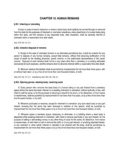
4 The variation in resistance withthe size of the plate is shown in Figure considering theresistivity of soil as 10 Wm. Since the ground resistance isproportional to the resistivity of soil, there would be differentparallel curves for the ground resistance for different valuesof resistivity of Pipe or rod groundingRefer to Figure In this case, the approximateresistance to ground in a uniform soil can be expressed by15 mm f GIwater pipeWire meshCast ironchamber coverFunnelInspection chamber1000 500 600 mmCementconcrete50 mm f GIwater pipeA homogenous layerof coke/charcoal/saltand sand1200 1200 12 mmCI plate2000mm1200mmNoteThe depth (2000 mm)
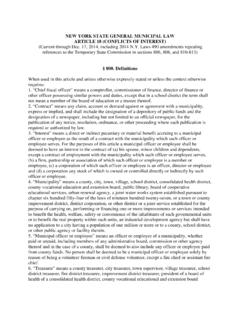
5 Would vary with themoisture content and quality of soilFigure typical layout of a plate electrodeFor r = 10 W mGround resistance (W) dimensions ( A m)( )Figure in resistance to ground with the linear dimensionsfor a plate grounding, for the same resistivity of soil22/800 Electrical Power Engineering Reference & Applications Handbook Rd = 100 2 log 8 1 e rp W( )where = length of pipe in cm d= internal diameter of pipe in cmNoteThe diameter, thickness and length of the pipe is recommended asfollows: Cast iron pipes 100 mm internal diameter, to 3 m long and13 mm thick. (This is a cumbersome and costlier arrangement,is not often used) MS pipes 38 to 50 mm diameter, to 3 m long (also notoften used) Copper or GI rods 13, 16 or 19 mm diameter, to type of electrode grounding is more suited for a soil possessinghigh resistivity, and the electrode is required to be longer and drivendeeper into the soil to obtain a lower resistance to ground.
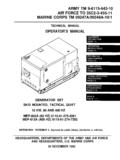
6 Theapproximate variation in resistance with the length of electrode fora particular value of resistivity of soil is shown in Figure , forgeneral resistance to ground of a 19 mm internal diameter pipe, m long, with r as 10 W mR = 100 102 244 log 8 1 Ohmse p= [loge 1]= [ 1] WFigure is drawn for r = 10 W Strip or round conductor groundingIn this case the approximate resistance to ground in auniform soil can be expressed by RhwQ = 1002 log 2 + Ohmse2rp ( )where =length of strip or rod in cm h =depth of the strip or rod in cmaw = width of the strip or diameter of the conductor rodin cmQ = 1 for strip and for round conductor minimum cross-sectional area of the strip or therod should be chosen according to the ground faultcurrent and its duration (Section and Equation( )).
7 The minimum area of cross-section isrecommended as For copper strip 25 mm2 For MS or GI strip 25 4 mm2 Figure variation of resistance to ground with thelength of pipe or a rod electrode for a particular value of resistivity of soilFor r = 10 Wm050100150200250300244 Length of electrode (cm)Resistance to ground (W) mmf GIwater pipeWire meshCast ironchamber coverFunnelInspectionchamber1000 500 600 mmCementconcreteA homogenous layerof coke/charcoal/saltand sand1250mm2500mm150mm150mm100 mm ID, CI pipe13 mm thickFigure typical arrangement of a pipe electrode groundingstationGrounding practices22/801 The performance of this type of electrode grounding isalmost the same as for the pipe grounding (Section )
8 As is the variation in resistance to the ground with thelength of the electrode as in Figure resistance to ground for a 100 mm 5 mm, 5 m copperstrip, buried at a depth of m, having a soil resistivity of100 WmR = 100 1002 500 log 2 500150 10 1e2 p= loge 1 = 1= WIf the length of the strip is 25 m, other parameters remainingthe same, thenR = 100 1002 2500 log 2 (2500)150 10 1e2 p= loge 1= 1= WNoteWe have considered a single length of electrode. If there is morethan one length the values can be obtained from BS 7430 for differentelectrode Numbers and types of groundingelectrodes1 The normal ground impedance in LV systems, isgenerally high.
9 To achieve a ground fault current ofthe order of 11/2 to 3 times the rated current, necessaryto protect a low current system against a ground faultas discussed in Section , would be difficult unlessadequate measures are taken with the groundingstations to have as low a ground impedance as achieve this, the grounding stations are madeelaborate, at adequate depth, with proper chemicaltreatment and watering arrangements to ensuresufficient moisture throughout the year. This is attainedby a perforated pipe driven from ground level up tothe electrode. See Figures and , showingtypical arrangements of a grounding station, with aplate grounding and a pipe grounding this, the ground resistance may still be toohigh to meet the design overcome this, a number of such groundingelectrodes (two being a bare minimum to provide adouble grounding system) may be essential andconnected in parallel to achieve the required lowvalue of ground resistance.
10 A cumulative resistanceof up to W is considered satisfactory. However,for more effectiveness and to make the groundprotective circuit more sensitive, a resistance of upto 1 W would be better. The grounding stations maybe separated, centre to centre, by 2 m or more, to beout of each other s resistance zone. A better gapwould be around to 6 m, when full groundresistance may be achieved by each electrode withoutinfringing on the resistance territory of the otherelectrodes as well as economizing on the number ofelectrodes. This use of more than one groundingstation in parallel so that each station is out of theresistance zone of the other stations, would alter theircumulative resistance, generally as follows accordingto Hand Book of Electrical Installation Practices byE.