Transcription of Control BLDC Motor Speed using PID Controller
1 (IJACSA) International Journal of Advanced Computer Science and Applications, Vol. 11, No. 3, 2020. Control bldc Motor Speed using PID Controller Md Mahmud1, S. M. A. Motakabber2, A. H. M. Zahirul Alam3, Anis Nurashikin Nordin4. Department of Electrical and Computer Engineering International Islamic University Malaysia Kuala Lumpur, Malaysia Abstract At present, green technology is a major concern in The structure of the bldc Motor tuning Control project every country around the world and electricity is a clean energy selection, modelling simulation and so on.
2 The design structure which encourages the acquisition of this technology. The main of a bldc Motor is a complex task and depends on many applications of electricity are made through the use of electric issues such as project selection, modeling, simulation, etc. In motors. Electric power is converted to mechanical energy using a terms of the rapidity framework of the bldc Motor , a host of Motor , that is to say, the major applications of electrical energy modern Control solutions have been proposed [3]. are accomplished through electric motors. brushless direct current ( bldc ) motors have become very attractive in many The key features of a conventional PID Controller algorithm applications due to its low maintenance costs and compact are it is easily adjustable, steady operation and its simple structure.
3 The bldc motors can be substituted to make the design, which making it widely used for controlling system. industries more dynamic. To get better performance bldc For practical reason, common Speed Control structure is applied Motor requires Control drive facilitating to Control its Speed and in the PID Controller . The mathematical model and Speed torque. This paper describes the design of the bldc Motor Control of the bldc Motor have been proposed and validated Control system using in using MATLAB/SIMULINK software for using fuzzy logic and PID Controller [4].
4 Most of the cases a Proportional Integral Derivative (PID) algorithm that can more different finding is seen in terms of practical utility experiences effectively improve the Speed Control of these types of motors. where the volatility of well-structured prototype, different units The purpose of the paper is to provide an overview about the of nonlinear, low variability have been at work. For tuning a functionality and design of the PID Controller . Finally, the study PID Controller parameters are not that simple, hence, getting undergoes some well-functioning tests that will support that the PID regulator is far more applicable, better operational, and the optimal position under the examined circumstances is effective in achieving satisfactory Control performance compared challenging [5].
5 This study proposes a PID Controller through to other controllers. modifying some changes thereto which, may increase the regulation Speed of bldc Motor . In this case parameters can Keywords PID Controller ; green technology; fuzzy logic be tuned at the actual moment under PID Controller operation. Control ; Speed Control ; bldc Motor In the sake of better functioning of the PID Controller scheme requires input and membership function enhancement [6]. At I. INTRODUCTION the same time, a set of values are applied for the PID. The present era is the era of the industrial revolution, which Controller 's constant coefficients, Kp, Ki and Kd.
6 By employing began with the invention of Motor . Various types of motors these values, the proposed modified Controller would be have been developed over time, but these motors are generally restructured to any adjusting dimension. classified into two main categories, namely, AC Motor and DC The purpose of this study is to show the dynamic response Motor . There exists a set of DC motors that can be used on to the rapid tuning results of the proposed modified PID. different devices. However, generally two types of DC motors Controller ; which can help to Control the Speed of the Motor and are set up in industrial applications.
7 In the first type, the to maintain constant Speed during load changes. Thus, the PID. magnetic flux is generated by the current through the field coil regulator can increase the overall performance of the bldc . of static pole structure and in the second type, permanent Motor . The simulation results showed that the functions of the magnet supplies the required air gap flux [1]. A bldc Motor PID Controller could be provided with a better Control is a special type of DC Motor that does not apply a brush for performance [7]. transport, instead an electronic process system is used for this purpose.
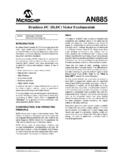
8 The bldc Motor is usually a synchronous Motor composed of a trapezoidal back EMF waveform and a permanent magnet. The current trend shows that high- performance bldc Motor technologies are widely used for global industrial applications and variable Speed drives in electric vehicles [2]. In fact, these types of motors depend on its Control circuit. In fact, these types of motors rely on its Control circuit and still developing a high performance circuit is a challenging task for researchers. A basic Control system is shown in Fig. 1 for the bldc Motor . Fig 1.
9 Basic Circuit Diagram for the bldc Motor Control System. 477 | P a g e (IJACSA) International Journal of Advanced Computer Science and Applications, Vol. 11, No. 3, 2020. II. bldc Motor AND Speed Control SYSTEM. A. Speed Control System A Controller circuit is essential to operate and Control the Speed of a bldc Motor . There are many types of Speed Control system developed for controllers but the Speed controllers have to modernize with the ages. However, they are generally classified as closed loop and open loop Control systems, respectively. Closed loop techniques are used for high accuracy Control system.
10 Fig. 2 shows a bldc Motor Speed Controller block diagram using two closed loop systems. In this case, the internal loop is used for tuning and sense the power supply polarity and the external loop is used to Control the Speed . The Motor Speed Controller helps to adjust the voltage of the DC. bus. To Control the system, DC supply is required and its value depends on the Motor Speed (rpm) and its capacity. This system also requires a Controller , in which case a PID Controller is used that ultimately controls the inverter output voltage. A. sensor is an integral part of a closed loop Controller for Fig 3.