Transcription of Control Of Three Phase Bldc Motor Using Fuzzy Logic Controller
1 Anjali. A. R M-Tech in Powerelectronics & Drives,Calicut University Abstract brushless DC (BLDC) Motor drives are becoming widely used in various consumer and industrial systems, such as servo Motor drives, home appliances, computer peripherals and automotive applications in recent years because of their high efficiency, silent operation, compact form, reliability and low maintenance. The aim of this research is to design a simulation model of Permanent Magnet brushless direct current (PMBLDC) Motor and to Control its position Using Fuzzy Logic Controller (FLC).
2 In this proposed Controller , mamdani method is used. In this project, a FLC for position Control and BLDC Motor are modeled and simulated in MATLAB/SIMULINK. Simulation results showed that Fuzzy Logic Control provides more efficient closed loop response for position Control of BLDC Motor . 1. Introduction BLDC motors are rapidly becoming popular in industries such as Appliances, HVAC industry, medical, electric traction, automotive, aircrafts, military equipment, hard disk drive, industrial automation equipment and instrumentation because of their smaller volume, high force, and simple system structure.
3 Many machine design and Control schemes have been developed to improve the performance of BLDC Motor drives. In practice, the design of the BLDCM drive involves a complex process such as modeling, Control scheme selection, simulation and parameters tuning etc. Recently, various modern Control solutions are proposed for the optimal Control design of BLDC Motor [1][2] .However, these methods are complex in nature and require excessive computation. In order to improve Control performance of the BLDC Motor drive, intelligence controllers such as Fuzzy Logic Control for BLDC Motor is used.
4 Design objectives that are difficult to express mathematically can be easily incorporated in a Fuzzy Controller by linguistic rules. In addition, its implementation is simple and straight forward. In this project, a complete simulation model with mamdani Fuzzy Logic Control method for BLDC Motor drive is proposed Using Matlab/Simulink. Section 2 describes mathematical modeling and the driving circuitry of BLDC Motor , section 3 explains the design of proposed Controller Using Mamdani method, section 4 gives the simulation results and section 5 concludes the paper.
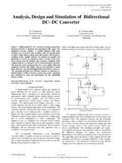
5 2. Mathematical modeling Figure 1 shows the basic building blocks of BLDC Motor and its Driving circuitry. Figure 1. Block diagram of BLDC Motor Control Of Three Phase BLDC Motor Using Fuzzy Logic Controller689 International Journal of Engineering Research & Technology (IJERT)Vol. 2 Issue 7, July - 2013 ISSN: The Y -connected, 3- Phase Motor with 8-pole permanent magnet rotor is driven by a standard Three Phase power convertor. The Motor specifications are given in Table 1 Table 1. BLDC Motor specifications Number of poles 8 Stator resistance ohms Stator inductance MH Rated torque 50 Nm Rated speed 140 deg/sec bandwidth 6-8 Hz Supply voltage 28 V Nominal current 11 A Sampling period 10 s Friction constant Kg-ms/rad Motor moment of inertia Kg-ms2/rad Figure 2 shows the complete Simulink model of Three Phase BLDC Motor with its controlling and driving circuitry.
6 The detailed description of the major blocks of BLDC Motor is mentioned below. Figure 2. Simulink model of BLDC Motor Electrical subsystem The electrical part of DC brushless Motor and relationship between currents, voltage, and back electromotive force androtor velocity is derived Using Kirchhoff s voltage law [3]: acacbabaaaaaedtdiMdtdiMdtdiLiRV bcbcababbbbbedtdiMdtdiMdtdiLiRV (1) cbcbacacccccedtdiMdtdiMdtdiLiRV Mechanical subsystem A mathematical relationship between the shaft angular velocity and voltage input to the DC brushless Motor is derived Using Newton s law of motion [6].
7 RmerFTTdtdJ (2) The angular position is obtained from an integration of the angular velocity. dtrr (3) Generated electromagnetic torque for this 3- Phase BLDC Motor is dependent on the current , speed and back-EMF waveforms, so the instantaneous electromagnetic torque can be represented as: ccbbaameieieie1T (4) Description of driving circuitry Driving circuitry consists of Three Phase power convertors as shown in Figure 3, which utilize six power transistors to energize two BLDC Motor phases concurrently.
8 The rotor position, which determines the switching sequence of the MOSFET transistors, is detected by means of 3 Hall sensors mounted on the stator. By Using Hall sensor information, Decoder block generates signal vector of back EMF. Figure 3. Three Phase power convertor In Reference current generator block, Fuzzy Logic Controller attempts to minimize the difference between desired angle and the actual measured angle by taking a corrective action to generate reference current signal. 690 International Journal of Engineering Research & Technology (IJERT)Vol. 2 Issue 7, July - 2013 ISSN: In current Control block shown in Figure 4, the reference current from current generator is transformed to reference voltage signal by Using Ohm s law (Vref= Iref R).
9 This reference voltage is then compared with the measured voltage across Control resistance Rc, where Rc= .When the measured voltage is less than the reference voltage, Control signal is set to one for t = 2Ts, where Ts is sampling time. In other case Control signal is set to zero. In this way a pulse width modulated (PWM) signal having fixed frequency with variable duty cycle is obtained. This PWM signal is then multiplied with the output from gate Logic to drive Three Phase Power Convertor. Figure 4. current Control block 3. Design of proposed Controller The structure of the proposed Controller for BLDC Motor is shown in Figure 5.
10 The proposed Controller consists of Fuzzy Logic Controller for position Control in the completed closed loop system. The designation of Fuzzy Logic Controller is based on expert knowledge which mean the knowledge of skillful operator during the handling of BLDC Motor system is adopted into the rule based design of Fuzzy Logic Controller . Figure 5. Proposed Controller There are four elements to be considered in order to design the Fuzzy Logic Controller which are fuzzification interface, Fuzzy rule, Fuzzy inference mechanism and defuzzification interface. Fuzzification The most important step in fuzzification interface element is to determine the state variables or input variables and the Control variables or output variables.