Transcription of Controller Area Network (CAN) - Electrical Engineering and ...
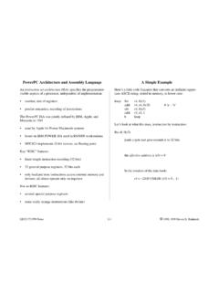
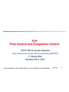
1 Controller area Network (CAN)EECS 461, Fall 2008 J. A. CookJ. S. Freudenberg1 IntroductionUp until now, we ve considered our embedded control system to be self-contained: an algorithm implementedin software resident on a single microprocessor, communicating with its environment through sensors andactuators via peripheral devices such as an analog-to-digital converter. In fact, many embedded systems aredistributed, consisting of multiple microprocessors communicating over one or more networks to accomplishshared tasks. For example, a modern automobile may have seventy or more microprocessors communicat-ing over several networks to manage entertainment and navigation functions, central locking mechanisms,lighting and other vehicle systems. Safety systems such as air bags employ dedicated high speed networkcommunication, as does powertrain control for communication between, for example, the engine and trans-mission controllers. Figure 1 illustrates some of the networks connecting automotive embedded systems[1, 2].
2 Although we will consider only wired networks, wireless is clearly a crucial technology for every-thing from assisted living to national defense [4], and wireless networking is a growing area of importanceto the twenty-first century automobile. Applications include toll collection, fleet vehicle management, stolenvehicle tracking, automatic collision notification and remote diagnostics. One may expect that the confluenceof in-vehicle and external communication technologies will lead to new information, entertainment and safetyservices such as the in-vehicle display of roadway emergency warnings or even active mitigation of collisionsat intersections and vehicle-to-vehicle cooperation for improvement of safety and traffic flow [3]. Open System Interconnection (OSI)It should be obvious that if two or more microprocessors are to communicate, a standardprotocolmustexist defining how data are to be transmitted among cooperating devices. The most common protocol isTCP/IP (Transmission Control Protocol/Internet Protocol), which is used to connect hosts on the TCP/IP was the Open Systems Interconnection (OSI) protocol initiated in 1982 by the Inter-national Organization for Standardization (ISO 7498-1:1994(E)).
3 The OSI protocol is sometimes referred toas the 7-layer model because it consists of seven independent elements that describe the requirements forcommunication at different levels of abstraction. The seven layers are:Application Layer:The application layer specifies how application programs access the Network . Exam-ples include email, file transfer, remote terminal access and web Layer:The presentation layer defines things like data compression and Layer:The session layer establishes, manages and terminates the connections between Layer:The transport layer provides transfer of data between users and addresses issues of errorcontrol and security. Revised October 13, ControlCentral Body ModuleStrg Column IgnitionOccupant Safety GatewayEngineTransmissionActive SuspensionDiagnostics GatewayInstrument Cluster P/T - Body GatewaySpeakerSpeakerRadioTripNavLow Speed CANHigh Speed CANMOSTF igure 1: Typical Automotive NetworksNetwork Layer:The Network layer performs Network routing Link Layer:The data link layer provides synchronization and error Layer:The physical layer defines the physical specifications for devices on the Network , includingconnectors, cables and Electrical specifications like voltage most commonly used Network for control in automotive and manufacturing applications is the ControllerArea Network , or CAN.
4 The CAN protocol specifies rules for implementing the physical and data link layersof the OSI model in silicon to effect serial transfer of information between two or more Controller area Network (CAN)The Controller area Network was developed by Robert Bosch GmbH for automotive applications in the early1980s and publicly released in 1986. The Bosch CAN specification became an ISO standard (ISO 11898) in1993 (CAN ), and extended in 1995 to permit longer device identifiers (CAN ) [5]. Typically, CANinterconnects a Network of modules (or nodes) using two wire, twisted pair cable. Many companies implementCAN devices. In the Freescale MPC 5xx series of processors, the CAN device is called the TouCAN module;in the MPC 55xx series it s called FlexCAN. CAN is a serial, multimaster, multicast protocol, which meansthat when the bus is free, any node can send a message (multimaster), and all nodes may receive and act onthe message (multicast). The node that initiates the message is called the transmitter; any node not sendinga message is called a receiver.
5 Messages are assigned static priorities, and a transmitting node will remaina transmitter until the bus becomes idle or until it is superseded by a node with a higher priority messagethrough a process called arbitration. A CAN message may contain up to 8 bytes of data. A message identifierdescribes the data content and is used by receiving nodes to determine the destination on the Network . Bitrates up to 1 Mbit/s are possible in short networks ( 40 m). Longer Network distances reduce the availablebit rate (125 kbit/s at 500 m, for example). High speed CAN is considered to be 500 CAN FundamentalsThe details of CAN are specified in [6]. In the following paragraphs, we will provide a brief description ofhow data are transmitted over CAN, how CAN messages are structured, and how transmission errors are2handled. There are four types of CAN messages, or frames: Data Frame, Remote Frame, Error Frame andOverload Frame. The data frame is the standard CAN message, broadcasting data from the transmitter tothe other nodes on the bus.
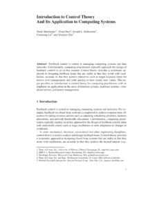
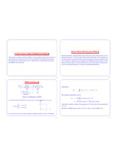
6 A remote frame is broadcast by a transmitter to request data from a specificnode. An error frame may be transmitted by any node that detects a bus error. Overload frames are used tointroduce additional delay between data or remote frames. CAN and data frames are illustratedin Figure 2 and in Tables 1 and 2. The difference between a CAN and a CAN message is thatCAN supports both 11 bit (standard) and 29 bit (extended) identifiers. Standard and extended framesmay exist on the same bus, and even have numerically equivalent identifiers. In this case, the standard framewill have the higher IdleArbitrationField11 Bit IdentifierSOFSOFBus IdleRTRRTRRTRr0 IDECRC DelimiterACK DelimiterACK SlotArbitrationFieldControlFieldDLCr1,r0 r1,r07 Bit EOF3 Bit INTACKData 0-8 BytesBus Idle11 Bit IdentifierDLCData 15 Bit CRCCAN Message FrameCAN Message Frame (Standard Format)SOFSRRIDEA rbitration FieldBus Idle11 Bit IdentifierDLCData CAN Message Frame (Extended Format)18 Bit ExtensionFigure 2: CAN Message FormatsTable 1: CAN Message FrameFieldLength (bits)DescriptionStart of Frame (SOF)1 Must be dominantIdentifier11 Unique identifier indicates priorityRemote Transmission Request (RTR)1 Dominant in data frames; recessive in remote framesReserved2 Must be dominantData Length Code (DLC)4 Number of data bytes (0 8)Data Field0 8 bytesLength determined by DLC fieldCyclic Redundancy Check (CRC)15 CRC Delimiter1 Must be recessiveAcknowledge (ACK)1 Transmitter sends recessive.
7 Receiver asserts dominantACK Delimiter1 Must be recessiveEnd of Frame (EOF)7 Must be recessive3 Table 2: CAN Message FrameFieldLength (bits)DescriptionStart of Frame (SOF)1 Must be dominantIdentifier Standard and ExtendedFormats11 Unique identifier corresponds to Base ID in ExtendedFormatIdentifier Extended Format29 Comprised of 11 bit Base ID and 18 bit Extended IDRemote Transmission Request (RTR) Standard and Extended Formats1 Dominant in data frames; recessive in remote frames. InStandard Format, the 11 bit identifier is followed by theRTR Remote Request (SRR) Extended Format1 Must be recessive. SRR is transmitted in ExtendedFrames at the position of the RTR bit in StandardFrames. In arbitration between standard and extendedframes, recessive SRR guarantees the standard messageframe Standard and Extended Frames1 Must be recessive for Extended Format; dominant forStandard r0 Standard Format1 Must be dominantReserved r1, r0 Extended Format2 Must be recessiveData Length Code (DLC)4 Number of data bytes (0 8)Data Field0 8 bytesLength determined by DLC fieldCyclic Redundancy Check (CRC)15 CRC Delimiter1 Must be recessiveAcknowledge (ACK)1 Transmitter sends recessive; receiver asserts dominantACK Delimiter1 Must be recessiveEnd of Frame (EOF)7 Must be The CAN Data FrameThe CAN data frame is composed of seven fields: Start of frame (SOF), arbitration, control, data, cyclicalredundancy check (CRC), acknowledge (ACK) and end of frame (EOF).
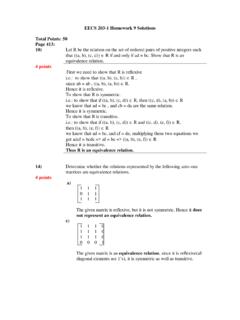
8 CAN message bits are referred toas dominant (0) or recessive (1). The SOF field consists of one dominant bit. All Network nodes waitingto transmit synchronize with the SOF and begin transmitting at the same time. Anarbitrationschemedetermines which of the nodes attempting to transmit will actually control the arbitration field of the CAN message consists of an 11- or 29-bit identifier and a remote transmission(RTR) bit. The CAN arbitration scheme is called carrier sense multiple access with collision detection or CSMA/CD, and assures that the highest priority message is broadcast. Message priority is determinedby the numerical value of the identifier in the arbitration field, with the lowest numerical value having thehighest priority. Non-destructive, bit-wise arbitration resolves conflicts among competing transmitters. Thismeans that the bus can be thought of as acting like an AND gate: If any node writes a dominant (0) bit onthe bus, every node will read a dominant bit regardless of the value written by that node.
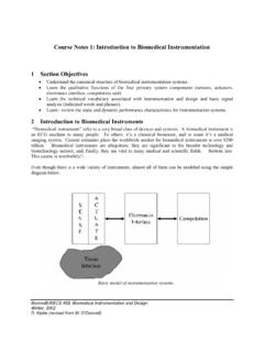
9 Every transmittingnode always reads back the bus value for each bit transmitted. If a node transmits a recessive bit and readsback a dominant bit, it immediately stops transmitting. Arbitration is illustrated in Figure RTR bit simply distinguishes between data frames and remote frames. In data frames, the RTRbit must be dominant; in remote frames it must be 1 loses arbitrationNode 1 Node 3 Node 2 Node 2 loses arbitrationFigure 3: CAN Arbitration: Node 3 has highest, and Node 1 the lowest, priority and Data FieldsThe control field of the data frame consists of 6 bits (of which only the lower 4 are used) that indicate theamount of data in the message. Since up to 8 bytes of data may be sent in one message, the control fieldmay take values ranging from 000000 to 000111. The data to be transmitted are contained in the data most significant bit (MSB) of a data byte is sent HandlingCAN implements five levels of error detection. At the message level, it performs cyclic redundancy checks,frame checks and acknowledgment checks.
10 Bit level checks consist of monitoring and redundancy errors are detected using a 15 bit CRC computed by the transmitter from the messagecontent. Each receiver accepting the message recalculates the CRC and compares it against the transmittedvalue. A discrepancy between the two calculations causes an error flag to be set. Frame checks that will flagan error are the detection by a receiver of an invalid bit in the CRC delimiter, ACK delimiter, EOF or 3-bitinterframe space. Finally, each receiving node writes a dominant bit into the ACK slot of the message framethat is read by the transmitting node. If a message is not acknowledged (perhaps because the receiver hasfailed), an ACK error is the bit level, we have already noted that each transmitted bit is read back by the transmitter. Ifthe monitored value is different than the value being sent, a bit error is detected. Additionally, bit errorsare detected by stuffing: After five consecutive identical bits have been transmitted, a bit of the oppositepolarity will be inserted ( stuffed ) by the transmitter into the bit stream (bits are stuffed from the SOFthrough the CRC field).