Transcription of Conveyor Chain - Designer Guide - renold.com
1 66engineering Chain Designer GUIDESECTION engineering excellence67 Designer Guide4 IntroductionSelecting the right Chain for a given application is essential toobtain long service life. This Guide has been developed for usewith Renold Conveyor Chain to help in specifying the right chainand lubrication for your Conveyor system. The significance of theRenold Conveyor Chain design is emphasised, followed byguidance on selection procedure. Detailed descriptions are givenof the various methods of application in a variety of mechanicalhandling problems and under widely varying conditions. Thesupporting material includes various reference tables the pyramids to the railway revolution, muscle-power of menand animals has moved goods and materials, but throughouthistory, machines, however primitive, have played some part,becoming more and more the immediate past, mechanical handling has emerged asa manufacturing industry in its own right, of considerable size andwith countless applications.
2 This is a consequence of itscoverage, which now ranges from the simplest store conveyorsystem to the largest flow line production layouts, and alsoincludes the movement of personnel by lifts, escalators the most widely used types of handling equipment areconveyors, elevators and similar assemblies. These can takemany forms, employing as their basic moving medium bothmetallic and non-metallic components or a mixture of the the great majority of applications Renold Conveyor Chain in itsmany variations, when fitted with suitable attachments, provides ahighly efficient propulsion and/or carrying medium, having manyadvantages over other types. Roller Chain has been employed asan efficient means of transmitting power since it was invented byHans Renold in 1880. Later the principle was applied to conveyorchain giving the same advantages of precision, heat-treatedcomponents to resist wear, high strength to weight ratio and highmechanical Conveyor Chain is made up of a series of inner and outerlinks.
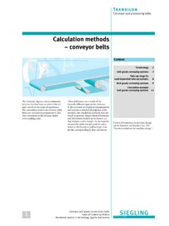
3 Each link comprises components manufactured frommaterials best suited to their function in the Chain ; the variousparts are shown in Figure 1. An inner link consists of a pair ofinner plates which are pressed onto cylindrical bushes, whilst oneach bush a free fitting roller is normally assembled. Each outerlink has a pair of outer plates which are pressed onto bearingpins and the ends of the pins are then rivetted over the the foregoing, it will be seen that a length of Chain is aseries of plain journal bearings free to articulate in one a Chain articulates under load the friction between pin andbush, whilst inherently low because of the smooth finish on thecomponents, will tend to turn the bush in the inner plates andsimilarly the bearing pin in the outer plate. To prevent this thebush and pin are force fitted into the Chain plates.
4 Close limits ofaccuracy are applied to the diameters of plate holes, bushesand bearing pins, resulting in high torsional security and rigidityof the mating components. Similar standards of accuracy applyto the pitch of the holes in the Chain ensure optimum wear life the pin and bush are hardened. Thebush outside diameter is hardened to contend with the loadcarrying pressure and gearing action, both of which are impartedby the Chain rollers. Chain roller material and diameter can bevaried and are selected to suit applicational conditions; guidancein roller selection is given on page 73. Materials used in chainmanufacture conform to closely controlled of components is similarly controlled bothdimensionally and with regard to heat a given pitch size of transmission Chain , there is normally agiven breaking load.
5 However, Conveyor Chain does not followthis convention. For each breaking load, Conveyor Chain hasmultiple pitch sizes available. The minimum pitch is governed bythe need for adequate sprocket tooth strength, the maximumpitch being dictated by plate and general Chain rigidity. Thenormal maximum pitch can be exceeded by incorporatingstrengthening bushes between the link plates, and suitable gapsin the sprocket teeth to clear these TYPEST here are two main types of Conveyor Chain - hollow bearing pinand solid bearing Bearing Pin ChainHollow pin Conveyor Chain offers the facility for fixing attachmentsto the outer links using bolts through the hollow pin andattachment, this method of fixing being suitable for use in mostnormal circumstances. The attachments may be bolted up tightor be held in a free manner.
6 Bolted attachments should onlyspan the outer link as a bolted attachment spanning the innerlink would impair the free articulation of the 168engineering Guide4 Solid Bearing Pin ChainSolid bearing pin Chain , while having exactly the same gearingdimensions in the BS series of Chain as the equivalent hollow pinchain, , inside width and roller diameter, is more robust witha higher breaking load and is recommended for use where morearduous conditions may be Link ChainHollow and solid pin Chain has an optional side plate designknown as deep link. This Chain s side plates have greater depththan normal, thus providing a continuous carrying edge above theroller STANDARDSC onveyor Chain , like transmission Chain , can be manufactured to anumber of different international standards. The main standardsavailable are:British Standard - BSThis standard covers Chain manufactured to suit the British marketand markets where a strong British presence has dominatedengineering design and purchasing.
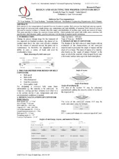
7 The standard is based on theoriginal Renold Conveyor Chain StandardChain manufactured to ISO standards is not interchangeable withBS or DIN standard Chain . This standard has a wide acceptance inthe European market, except in Germany. Chain manufactured tothis standard is becoming more popular and are used extensivelyin the Scandinavian ATTACHMENTSAn attachment is any part fitted to the basic Chain to adapt it for aparticular conveying duty, and it may be an integral part of thechain plate or can be built into the Chain as a replacement for thenormal AttachmentsThese are the most popular types of attachment, being used onslat and apron conveyors, bucket elevators etc. As shown in they provide a platform parallel to the Chain and bearing pinaxes. They are used for securing slats and buckets etc.
8 To thechain. Either one or two holes are normally provided in theplatform, being designated K1 or K2 respectively. K attachmentscan be incorporated on one or both sides of the Chain . For themore important stock pitches where large quantities justify the useof special manufacturing equipment, the attachments areproduced as an integral part of the Chain , as shown in Fig. 2(a).Here the platform is a bent over extension of the Chain plate other Chain or where only small quantities are involved, separateattachments are used, as shown in Fig. 2(b). These are usuallywelded to the Chain depending on the particular Chain series andthe application. Alternatively, (see Fig 2(c)), K attachments may bebolted to the Chain either through the hollow bearing pins, or byusing special outer links with extended and screwed bearing pinends.
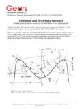
9 (a) K1 bent over attachment.(b) K1 attachment, welded to link plate.(c) K2 attachment bolted through hollow bearing AttachmentsThese attachments as shown in Fig. 3 are frequently used forpusher and scraper applications. They comprise a wing with avertical surface at right angles to the Chain . They can be fitted toone or both sides and are usually secured by welding. Each wingcan be provided with one or two holes, being designated F1 or F2respectively.(a) F1 attachments welded to link plates on one or both sides ofthe Chain as required.(b) F2 attachments welded to link plates on one or both sides ofthe Chain as Pins and ExtendedBearing PinsBoth types are used on pusher and festoon conveyors and trayelevators, etc. Spigot pins may be assembled through hollowbearing pins, inner links or outer links.
10 When assembled throughlink plates a spacing bush is necessary to ensure that the insidewidth of the Chain is not reduced. Gapping of the sprocket teeth isnecessary to clear the bearing pin chains can have similar extensions at the pitchpoints by incorporating extended pins. Both spigot pins andextended pins, as shown in Fig. 4, can be case-hardened on theirworking diameters for increased wear resistance.(a) Spigot pin assembled through outer or inner link.(b) Spigot pin bolted through hollow bearing pin.(c) Extended bearing 2 Fig. 3 Fig. engineering excellence69 Designer Guide4 StaybarsTypes of mechanical handling equipment that use staybars arepusher, wire mesh, festoon conveyors, etc., the staybars beingassembled in the same manner as spigot pins. When assembledthrough link plates a spacing bush and gapping of the sprocketteeth are plain bar-and-tube type shown in Fig.