Transcription of cosmo 4PIN PHOTODARLINGTON …
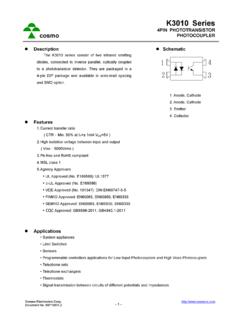
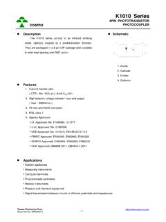
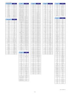
1 cosmo Electronics Corp. Document No. - 1 - cosmo KP4010 Series 4 PIN PHOTODARLINGTON photocoupler Description The KP4010 series consist of a PHOTODARLINGTON optically coupled to a gallium arsenide infrared-emitting diode in a 4-pin DIP package and available in wide-lead spacing and SMD option. Collector-emitter voltage is 300V. It features a high current transfer ratio, low coupling capacitance and high isolation voltage. Schematic 2134 1. Anode 2. Cathode 3. Emitter 4. Collector Features 1. High current transfer ratio (Vceo: 300V min.) ( CTR Min. 600% at IF=1mA VCE=2V ) 2. High isolation voltage between input and output ( Viso 5000 Vrms ) 3. Compact dual-in-line package 4. Pb free and RoHS compliant 5. MSL class 1 6.
2 Agency Approvals UL Approved (No. E169586): UL1577 c-UL Approved (No. E169586) VDE Approved (No. 101347): DIN EN60747-5-5 FIMKO Approved: EN62368-1, EN60601-1 CQC Approved: GB8898-2011, Applications System appliances, measuring instruments Industrial robots Copiers, automatic vending machines, facsimiles Signal transmission between circuits of different potentials and impedances Telephone sets Numerical control machines Interface with various power supply circuits, power distribution boards cosmo Electronics Corp. Document No. - 2 - cosmo KP4010 Series 4 PIN PHOTODARLINGTON photocoupler Outside Dimension Unit : mm ~10 ~10 + mount creepage distance creepage distance for surface mount type.
3 Device Marking Notes: cosmo 4010 YWW Y: Year code / WW: Week code : CTR rank cosmo4010 YWW cosmo Electronics Corp. Document No. - 3 - cosmo KP4010 Series 4 PIN PHOTODARLINGTON photocoupler Absolute Maximum Ratings (Ta=25 C) Parameter Symbol Rating Unit Input Forward current IF 50 mA Peak forward current IFM 1 A Reverse voltage VR 6 V Power dissipation PD 70 mW Output Collector-emitter voltage VCEO 300 V
4 Emitter-collector voltage VECO V Collector current IC 150 mA Collector power dissipation PC 200 mW Total power dissipation Ptot 200 mW Isolation voltage 1 minute Viso 5000 Vrms Operating temperature Topr -55 to +115 C Storage temperature Tstg -55 to +125 C Soldering temperature 10 seconds Tsol 260 C Electro-optical Characteristics (Ta=25 C) Parameter Symbol Conditions Min.
5 Typ. Max. Unit Input Forward voltage VF IF=20mA - V Peak forward voltage VFM IFM= - - V Reverse current IR VR=4V - - 10 A Terminal capacitance Ct V=0, f=1 KHz - 30 - pF Output Collector dark current ICEO VCE=200V - - A Transfer charac- teristics Current transfer ratio CTR IF=1mA, VCE=2V 600 - 9000 % Collector-emitter saturation VCE(sat)
6 IF=20mA, IC=5mA - - V Isolation resistance Riso DC500V 5x10¹⁰ - - Floating capacitance Cf V=0, f=1 MHz - pF Cut-off frequency fC VCC=5V, IC=2mA, RL=100 - 7 - KHz Response time (Rise) tr VCE=2V, IC=20mA, RL=100 - 60 300 s Response time (Fall) tf - 50 250 s cosmo Electronics Corp. Document No.
7 - 4 - cosmo KP4010 Series 4 PIN PHOTODARLINGTON photocoupler Classification table of current transfer ratio is shown below. KP4010 Model No. CTR ( % ) KP4010 A 600 ~ 2000 KP4010 B 1500 ~ 4000 KP4010 C 3000 ~ 6000 KP4010 D 5000 ~ 9000 KP4010 E 600 ~ 9000 Current Transfer Ratio vs. Forward Current Current Transfer Ratio CTR ( % ) 'CV =2 VCE Forward Current IF (mA) Collector Power Dissipation Collector Dark Current vs. Ambient Temperature vs. Ambient Temperature Collector Power Dissipation PC ( mW ) 250-555001001257550200150250115 Collector Dark Current ICEO ( A ) -810-5502510-1110-10-910V =200V10-710-610-57550115CE Ambient Temperature Ta ( C) Ambient Temperature Ta ( C) Forward Current Forward Current vs. Ambient Temperature vs. Forward Voltage Forward Current IF ( mA ) 6010-550200253040505075115 125 Forward Current IF ( mA ) Ta=75 C0 1 Ambient Temperature Ta ( ) C Forward Voltage VF (V) cosmo Electronics Corp.
8 Document No. - 5 - cosmo KP4010 Series 4 PIN PHOTODARLINGTON photocoupler Collector Current Relative Current Transfer Ratio vs. Collector-Emitter Voltage vs. Ambient Temperature Collector Current IC (mA) =10mA100F5mATa=25' Relative Current Transfer Ratio ( % ) -250050255011575I = 1m AV =2V150100 FCE Collector-Emitter Voltage VCE (V) Ambient Temperature Ta ( ) C Collector-Emitter Saturation Response Time (Rise) Voltage vs. Forward Current vs. Load Resistance Collector-Emitter Saturation Voltage VCE ( V ) 050101235467 CTa=25 Ic=7m AIc=5m AIc=3m AIc=1m AIc= A Response Rise Time ( us ) 1 2 5 10 20100 50Ic=2m AV =2 VTa=25 CCE Forward Current IF (mA) Load Resistance RL (K ) Response Time (Fall) vs. Load Resistance Response Fall Time ( us ) 5 2 20 10Ta=25 Ic= 2 m AV =2V100 50 CtfCE Load Resistance RL (K ) cosmo Electronics Corp.
9 Document No. - 6 - cosmo KP4010 Series 4 PIN PHOTODARLINGTON photocoupler Test Circuit for Response Time Vcetrtf90%10%2134 RVccVceIFIFL cosmo Electronics Corp. Document No. - 7 - cosmo KP4010 Series 4 PIN PHOTODARLINGTON photocoupler Recommended Soldering Conditions (a) Infrared reflow soldering Peak reflow soldering Time of peak reflow temperature Time of temperature higher than 230 C Time to preheat temperature from 180~190 C Time(s) of reflow Flux 260 C or below (package surface temperature) 10 sec 30-60 sec 60-120 sec Two Rosin flux containing small amount of chlorine (The flux with a maximum chlorine content of Wt% is recommended.) Recommended Temperature Profile of Infrared Reflow 180 C190 C230 C260 C60-120 sec30-60 sect (s)temperature10 sec M ax.
10 (b) Wave soldering Temperature Time Preheating conditions Time(s) of reflow Flux 260 C or below (molten solder temperature) 10 seconds or less 120 C or below (package surface temperature) One Rosin flux containing small amount of chlorine (The flux with a maximum chlorine content of Wt% is recommended.) (c) Cautions Fluxes Avoid removing the residual flux with freon-based and chlorine-based cleaning solvent. Avoid shorting between portion of frame and leads. cosmo Electronics Corp. Document No. - 8 - cosmo KP4010 Series 4 PIN PHOTODARLINGTON photocoupler Numbering System KP4010 X Y (Z) Notes: KP4010 = Part No. X = Lead form option (1,2,3,6) Y = CTR rank option (A ~ E) Z = Tape and reel option (TLD, TRU) Option Description Packing quantity 2 (TLD) surface mount type package + TLD tape & reel option 2000 units per reel 2 (TRU) surface mount type package + TRU tape & reel option 2000 units per reel 6 (TLD) long creepage distance for surface mount type package + TLD tape & reel option 2000 units per reel 6 (TRU) long creepage distance for surface mount type package + TRU tape & reel option 2000 units per reel Recommended Pad Layout for Surface Mount Lead Form Unit.