Transcription of CRITERIA FOR TEMPERATURE SENSOR SELECTION …
1 Acromag, Incorporated 30765 S Wixom Rd, PO Box 437, Wixom, MI 48393-7037 USA Tel: 248-295-0880 Fax: 248-624-9234 Copyright Acromag, Inc. May 2011 8500-917-A11E000 Trademarks are the property of their respective owners. CRITERIA FOR TEMPERATURE SENSOR SELECTION OF T/C AND RTD SENSOR TYPES The Basics of TEMPERATURE Measurement Using RTDs Part 2 of 3 CRITERIA FOR TEMPERATURE SENSOR SELECTION OF T/C AND RTD SENSOR TYPES Part 2 of 3: The Basics of TEMPERATURE Measurement Using RTDs 2 This is part two of a three part series that provides information for choosing an industrial TEMPERATURE SENSOR from Thermocouple (T/C) and Resistance TEMPERATURE Detector (RTD) SENSOR types.
2 Part 1 of this series took a close look at thermocouples. This part will look similarly at RTDs. After a review of the basic construction of an RTD, we will take look at an RTDs TEMPERATURE Coefficient of Resistance (TCR), its sensitivity, accuracy, interchangeability, repeatability, stability and drift, corrosion and contamination effects, shock and vibration effects, insulation resistance, lead-wire resistance, self-heating effects, meter-loading, packaging and thermal transfer considerations, response time, and thermoelectric effects. In part 3 of this series, we will summarize and compare the thermocouple and RTD SENSOR types, and provide information for selecting the best SENSOR for a given application.
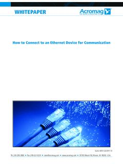
3 The Basics of Resistance TEMPERATURE Detectors An RTD or Resistance TEMPERATURE Detector is a passive circuit element whose resistance increases with increasing TEMPERATURE in a predictable manner. The traditional RTD element is constructed of a small coil of platinum, copper, or nickel wire, wound to a precise resistance value around a ceramic or glass bobbin. The winding is generally done using one of two styles: birdcage or helix. The birdcage winding keeps the platinum wire loosely wound on the bobbin allowing it to expand and contract freely over TEMPERATURE in order to minimize any stress-induced change in resistance.
4 This style of winding is generally limited to laboratory use as it has poor resistance to shock and vibration. The helix wire-wound RTD uses a bifilar wound coil wrapped around a bobbin and then sealed with molten glass, ceramic cement, or some other high- TEMPERATURE insulating coating. The helix winding style helps protect the wire element from shock and vibration induced changes to its resistance, but it may still be prone to stress induced resistance change due to the different coefficients of thermal expansion of the wire coil and bobbin material. Image source: Burns Engineering CRITERIA FOR TEMPERATURE SENSOR SELECTION OF T/C AND RTD SENSOR TYPES Part 2 of 3: The Basics of TEMPERATURE Measurement Using RTDs 3 More recently, RTDs are also being constructed using a thin-film of platinum or nickel-iron metal deposited on a ceramic substrate and then laser-trimmed to a desired reference resistance.
5 The advantage offered by this construction is that the thin-film elements can achieve a higher resistance with less metal, and over smaller areas. This makes them smaller, cheaper, and faster responding than their older wire-wound counterparts. The most common RTD element material is Platinum, as it is a more accurate, reliable, chemically resistant, and stable material, making it less susceptible to environmental contamination and corrosion than the other metals. It s also easy to manufacture and widely standardized with readily available platinum wire available in very pure form with excellent reproducibility of its electrical characteristics.
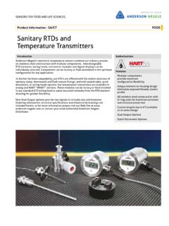
6 Platinum also has a higher melting point, giving it a wider operating TEMPERATURE range. RTD Sensing Element Material and Relative TEMPERATURE Limits RTD ELEMENT MATERIAL USABLE TEMPERATURE RANGE Platinum -260 C to +650 C Nickel -100 C to +300 C Copper -75 C to +150 C Nickel/Iron 0 C to +200 C For an RTD SENSOR .
7 It is the wires which connect to the sensing element and the wire insulation which generally limits the maximum application TEMPERATURE of the SENSOR . The following table lists common wire and insulation materials and their maximum rated usage TEMPERATURE : Image source: Burns Engineering CRITERIA FOR TEMPERATURE SENSOR SELECTION OF T/C AND RTD SENSOR TYPES Part 2 of 3: The Basics of TEMPERATURE Measurement Using RTDs 4 RTD Sensing Element Material and Relative TEMPERATURE Limits WIRE/INSULATION MATERIAL USABLE TEMPERATURE RANGE Tinned Copper/PVC Insulation +105 C Silver Plated Copper/FEP Teflon Insulation +205 C Silver Plated Copper/TFE Teflon Insulation +260 C Nickel Plated Copper/TFE Teflon Insulation +260 C Nickel Plated Copper/Fiberglas Insulation +480 C Solid Nickel Wire/No Insulation +650 C Measuring the TEMPERATURE of an RTD involves measuring this resistance accurately.
8 To measure the resistance, it is necessary to convert it to a voltage and use the voltage to drive a differential input amplifier. The use of a differential input amplifier is important as it will reject the common mode noise on the leads of the RTD and provide the greatest voltage sensitivity. The RTD signal is generally measured one of two ways: either by connecting the RTD element in one leg of a Wheatstone bridge excited by a constant reference voltage, or by running it in series with a precision current reference and measuring the corresponding IR voltage drop. The latter method is generally preferred as it has less dependence on the reference resistance of the RTD element.
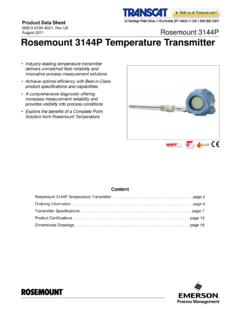
9 The following figures denote some of the ways that RTD signals are sensed by mating instruments. Figure 1A shows a typical 2-wire connection. This method is limited to short distances between the SENSOR and measuring instrument because it does not compensate for lead-wire resistance. Excitation current flows through the sense leads and the resultant IR drop is included in the measurement. Figure 1B uses a Wheatstone bridge to connect to a 2-wire SENSOR , and adds lead-wire compensation, but has the disadvantage of requiring that the bridge resistance match the base resistance of the SENSOR . Figure 2A shows a traditional 3-wire connection which adds lead-wire compensation for matched leads, but it requires two measurements to convert the RTD signal.
10 Figure 2B uses dual matched current sources to excite the 3-wire SENSOR , one at each lead. As long as the leads match, the IR drop in the leads does not affect the measurement. This has the added advantage of converting the RTD signal in a single differential measurement. In addition, only the leads to the SENSOR must match, as the third lead is just a return current path for the combined excitation currents. Figure 3A provides the most exacting method of conversion, 4-wire with Kelvin connections, but it needs four points of connection to the SENSOR . No current flows into the sense leads so the lead wires do not need to be matched.