Transcription of CS429: Computer Organization and Architecture - …
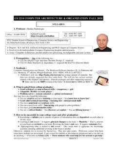
1 cs429 : Computer Organization and ArchitectureLogic DesignDr. Bill YoungDepartment of Computer ScienceUniversity of Texas at AustinLast updated: February 17, 2020 at 13:55CS429 Slideset 5: 1 Logic DesignTopics of this SlidesetTo execute a program we need:Communication:getting data from one place to anotherComputation:perform arithmetic or logical operationsMemory:store the program, variables, resultsEverything is expressed in terms of : Low or high voltage on a wireComputation: Compute boolean functionsStorage: Store bitsCS429 Slideset 5: 2 Logic DesignDigital SignalsUse voltage thesholds to extract discrete values from acontinuous version: 1-bit signalEither high range (1) or low range (0)With a guard range between strongly affected by noise or low-quality elements; circuitsare simple, small and Slideset 5: 3 Logic DesignTruth TablesAnd:A & B= 1 when both A =1 and B = B&0 000 101 001 11Or:A|B= 1 when either A =1 or B = B|0 000 111 011 11 Not: A= 1 when A = 0110 Xor:A B= 1 when either A= 1 or B = 1, but not B 0 000 111 011 10CS429 Slideset 5: 4 Logic DesignGatesWhat does it mean for a hardware device to represent a booleanfunction (or truth table), sayand?
2 cs429 Slideset 5: 5 Logic DesignGatesWhat does it mean for a hardware device to represent a booleanfunction (or truth table), sayand?1 Place on the two input lines voltages representing logicalvalues (T or F).2 After a shortdelay, the output line will stabilize to a voltagerepresenting the logicalandof the Slideset 5: 6 Logic DesignComputing with Logic GatesHow are these logic functions actually computed in hardware?Logic gates are constructed from output is a boolean function of gate responds continuously to changes in inputwith asmall many of these do you really need? cs429 Slideset 5: 7 Logic DesignAside: Multiple-Input GatesSome gates allow multiple inputs. For example, a 3-input ANDisessentially just a cascade of two 2-input which gates does it make sense to have extra inputs? Forwhich doesn t it make sense? cs429 Slideset 5: 8 Logic DesignAside: Inverted Inputs/OutputsA small circle on either the input or output of a gate means thatthat signal is inverted.
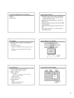
3 That is, it s as if there were an inverter(not) gate would animpliesgate look like? cs429 Slideset 5: 9 Logic DesignA Complex FunctionPrimitive boolean functions areimplemented by logic gates; morecomplex functions, bycombinations of = !A || (B ABCZ00010011010101111000101011001111CS42 9 Slideset 5: 10 Logic DesignAnother CircuitWhich wires are connected and which are not? Can you see whatthis circuit does? cs429 Slideset 5: 11 Logic DesignAnother CircuitWhich wires are connected and which are not? Can you see whatthis circuit does?This is called amajority circuit. What function does it compute? cs429 Slideset 5: 12 Logic DesignSets of Logic GatesIt s pretty easy to see that any boolean function can beimplemented with AND, OR and call that afunctionally completeset of can get by with fewer would you show each of thefollowing?AND and NOT is and NOT is is is alone is not alone is not circuit designers will restrict themselves to a smallsubset ofgates ( , just NAND gates).)
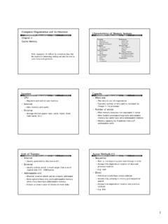
4 Why would they do that? cs429 Slideset 5: 13 Logic DesignUsing Logic for ArithmeticSuppose you wanted to do addition with might you goabout that? cs429 Slideset 5: 14 Logic DesignUsing Logic for ArithmeticSuppose you wanted to do addition with might you goabout that?Define a circuit (full adder) that does one step in an addition:FullAddercarry incarry outSABABCinCoutS000001010011100101110111 cs429 Slideset 5: 15 Logic DesignFull AdderThe following circuit is a fulladder:A half adder is a simpler circuitwith only inputs A and Slideset 5: 16 Logic DesignAdding a Pair of 4-bit IntsHow do you subtract? How do you multiply? cs429 Slideset 5: 17 Logic DesignCombinational CircuitsThe box contains an acyclic network of logic responds to changes in become (after a short delay) boolean functions of Slideset 5: 18 Logic DesignBit EqualityThe following circuit generates a 1 iff a and b are eq = (a&&b) || (!a Can you design a simpler circuit to do this?Hardware description languages (Verilog, VHDL)Describe control, data movement.)
5 Compile (synthesize) a hardware description into a Slideset 5: 19 Logic DesignVerilog ExampleOne of the more widely used HDL s is Verilog:module s i m pc i r c u i t (A, B, C, x , y ) ;input A, B, C;output x , y ;wire e ;and g1 ( e , A, B) ;not g2 ( y , C) ;or g3 ( x , e , y ) ;endmoduleCS429 Slideset 5: 20 Logic DesignHCLH ardware Control Language (HCL)Very simple hardware description operations have syntax similar to C logical ll use it to describe control logic for typesbool: Boolean ( a, b, c, .. )int: words ( A, B, C, .. )Does not specify word sizeStatementsbool a = bool-expr;int A = int-expr; cs429 Slideset 5: 21 Logic DesignHCL OperationsBoolean expressionsLogic operations:a && b,a || b,!aWord comparisons:A == B,A != B,A < B,A <= B,A >= B,A > BSet membership:A in {B, C, D}Word expressionsCase expressions:[a: A; b: B; c: C]Evaluate Boolean expressionsa, b, cin sequenceReturn corresponding word expression for first successfulBoolean Slideset 5: 22 Logic DesignWord EqualityBit equalBit equalBit equalBit representation:=EqBAHCL Representation:Eq = (A == B)Assume 32-bit word representationEquality operationGenerates Boolean valueCS429 Slideset 5: 23 Logic DesignBit MultiplexorOutabSHCL Expression:int out = (s && a) || (!)
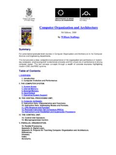
6 S Control signal s selects between two inputs a and is a whens == 1, and b Slideset 5: 24 Logic DesignWord representation:ABSOutMuxHCL Representation:int Out = [s : A;1 : B;];Select input word A or Bdepending on control signal Slideset 5: 25 Logic DesignWord ExamplesMinimum of 3 words4 way MultiplexorMIN3 MUX4 Out4 Min3 CBAS1S0D1D2D3D0int Min3 = [A <= B && A <= C : A;B <= A && B <= C : B;1: C;]int Out4 = [!s1 && !s0 : D0;!s1: D1;!s0: D2;1: D3;]What do these do? cs429 Slideset 5: 26 Logic DesignConstructing an ALUAn ALU is an Arithmetic Logic UnitMultiple functions:add,subtract,and,xor, othersCombinational logic to perform signals select function to be : multiple instances of 1-bit ALUCS429 Slideset 5: 27 Logic DesignA 4-bit ALUC ombinational logic: continuously responding to signal selects function computed; Y86 ALU has only 4arithmetic/logical computes values of condition codes. Note these are notthe same as the three Y86 flags:OF: overflow flagZF: zero flagSF: sign flagCS429 Slideset 5: 28 Logic DesignThe Y86 ALU in HCLALUOFZFSFXYALUOFZFSFXYALUOFZFSFXYALUOFZFSFXYX+YX YX&YX^Y<s1,s0>=00<s1,s0>=01<s1,s0>=10<s1,s0>=11int Out = [!]
7 S1 && !s0: X+Y;!s1 && s0 : X-Y;s1 && !s0: X&Y;1: X Y;]; cs429 Slideset 5: 29 Logic DesignSequential LogicHow would you design a circuit that records a bit? What does thateven mean? cs429 Slideset 5: 30 Logic DesignSequential LogicHow would you design a circuit that records a bit? What does thateven mean?Ideally, you d like abi-stabledevice (latch)as follows: EnableQDataThe value on lineQisthe current stored store a new value:1 LineEnableshould be low (0).2 Place the bit to store on high (1).4 The value on lineDatais stored inthe low (0).6 ReadingQreturns the stored bituntil next state-holding devices are calledsequential logicas opposedtocombinational Slideset 5: 31 Logic DesignSR Flip Flop: Storing a BitAn SR flip flop is a step in thedirection of a (temporarily raise) the R(reset) input to record a the S (set) input to recorda tableSRQnextAction00 Qhold state010reset101set11 Xnot allowedThis is not very convenient because it requires pulsing either S orR to record a Slideset 5: 32 Logic DesignGated D Latch: Store and Access One Bit_QQDCPH igher level representationD Latch Truth tableE/CPDQQC omment0 XQQNo change1001 Reset1110 SetE (enable) and CP (clock pulse) are just twonames for the same Slideset 5: 33 Logic DesignA 4-bit Register4 D latches:All share the E/CP (aka WEor Write Enable) inputD0 D3 are the data inputQ0 Q3 are the output_Q_Q_Q_QQDCPQDCPQDCPQDCPCPD2D3D1D0 Q0Q1Q2Q3CS429 Slideset 5.
8 34 Logic DesignRegister File AbstractionRegister file provides the CPUwith temporary, fast of K output we want eight 4-bitregisters and one output inReg/3/4/1 Data out/4CS429 Slideset 5: 35 Logic DesignRace-through Condition with D LatchesWrite Enable (WE) must be held at 1 long enough to allow:Data to be read;Operation ( , addition) to be performed;Result to be stored in target Slideset 5: 36 Logic DesignEdge Triggered Flip FlopsAn edge-triggered flip-flop changes states either at the positiveedge (rising edge) or at the negative edge (falling edge) of theclock pulse on the control register is made up of several flip flops, each providingstorage and access for an individual register file is made up of several registers and control logicCS429 Slideset 5: 37 Logic DesignClockingThe clock acts to enforce timing control on the integral part of every synchronous be globalClock Frequency = 1 / clock periodMeasured in cycles per second (Hertz)1 KHz = 1000 cycles / second1ns (10 9seconds) = 1 GHz (109) clock frequencyHigher frequency means faster machine Slideset 5.
9 38 Logic DesignRandom Access Memory (RAM)Stores many wordsConceptually, a large array where each row is reality, much more complex to increase chips and banks, interleaved, with implementationsDynamic (DRAM) is large, inexpensive, but relatively transistor and 1 capacitor per are periodic time takes hundreds of CPU (SRAM) is fast but transistors per Slideset 5: 39 Logic DesignSummaryComputationPerformed by combinational boolean reacts to : part of the holds a single for temporary results of on rising is much of implementation Slideset 5: 40 Logic Desig