Transcription of Cummins ISL-G
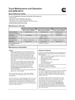
1 Cummins ISL-G . Webinar Moderator Jerry Guaracino Deputy Chief Engineering Officer Southeastern Pennsylvania Transportation Authority (SEPTA). Philadelphia, PA. Presenters Obed Mejia Victoria Chesney Senior Bus Equipment Maintenance Instructor Maintenance Supervisor Los Angeles Metropolitan Transportation Authority Omnitrans Los Angeles, CA San Bernardino, CA. Objectives Participants on today's webinar will learn how to: Identify Maintenance Procedures Examine components to meet specifications Perform maintenance practices to OEM specifications Related APTA Standards APTA BTS-BMT-RP-008-16: Training Syllabus to Instruct Bus Technicians on EPA Emissions Standards and Treatment Technologies For additional resources visit: Fleet Facts Metro Omnitrans 2400+ Buses in service 187 Fixed Route Coaches 2300 ISL-G 22 Cummins C+.
2 100 L Gas Plus 43 John Deere HFN04. 122 Cummins ISL G. Revenue Miles 90 million per year Service area of 456 sq. miles with just over 9 million miles run per year. Operating Parameters Maximum Horsepower 320 HP. Peak Torque 1000 LB-FT. Governed Speed 2200 RPM. Engine Displacement 540 CU IN LITERS. spark-ignited, in-line 6-cylinder, turbocharged, CAC. Fuel Type CNG/LNG/RNG Methane number75 or greater Aftertreatment Three-Way Catalyst (TW. Engine Management System The control system for the ISL-G engine is a closed loop control system. The electronic control module controls the throttle plate and fuel control valve to provide the correct fueling and spark timing.)
3 The ISL-G engine through the years has been built with several potential sensor configurations and terminology variances. Ensure that you are using the latest software version to correctly interact with control system. Control System Components Control System Components Ignition System Capacitive discharge system. The ICM (Ignition Control Module) steps 12V input and steps up to 250-300V. to the primary side of the coil. CNG Fuel Flow - Sample EGR System The EGR system is responsible for re- circulating metered exhaust gas back into the combustion chamber.
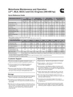
4 This is done to cool down the chamber temperature by introducing inert gas. Nitric Oxides emissions are formed when engine chamber temperatures rise above 2500 F. Keeping the chamber cool reduces NOx emission. System Components: EGR valve, cooler, flow and temperature sensors. EGR Cooler 1. The cooler cools the exhaust gas before it's recirculated into the intake manifold. This assist in reducing the combustion chamber temperature. The cooler circulates engine coolant through the EGR as a heat exchange medium. Currently there are two styles in 2.
5 Use. Horizontal Plate square style (illustration 1). Circular style (illustration 2). Maintenance Procedures Spark Plug R&R Procedure Removal: Do not wiggle coil brackets when removing coils remove straight up Remove spark plug with a magnetic socket Blow-Out Spark Plug cavity Spark Plug R&R Procedure Installation: Check Plug Gap do not adjust/do not install if out of gap Prior to installation spark plug must be cleaned with alcohol pad or swab. Dirt, oil, and fingerprints reduce the seal strength between the spark plug boot and the porcelain causing reduced spark plug life.
6 Spark Plug R&R Procedure Installation: Remove old boot from coil extension Inspect coil for cracks or evidence of arcing Clean coil extension Install new spark plug boots to coils, new boots come with dielectric grease from the factory. If boots do not have dielectric grease, apply a small amount. Spark Plug R&R Procedure Installation: Install new spark plugs using clean magnetic spark plug socket. Torque spark plug to 28 ft-lb (35 Nm). Failure to torque spark plugs will result in engine misfire and premature spark plug failure. Proper torque aids in heat dissipation Acceptable Spark Reuse - Cummins Consult Cummins Quikserve for latest TSB's Not-Acceptable Spark Reuse - Cummins Consult Cummins Quikserve for latest TSB's Valve Adjustment Procedures General Knowledge: valve adjustments are a critical part of the preventive maintenance and the bus repair process.
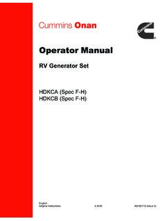
7 During the procedure; keep in mind: Engine should be at 140 F or less. Check valve height valve may recess into head causing performance complaints Check the rocker shafts for wear this may cause the rocker to bind Valve Adjustment Procedure Overlap Method: 1. Rotate engine until valve overlap is reached on cylinder #6. Valve overlap is when both the intake and exhaust valves are opened at the same time. You will notice that as the exhaust valve is closing the intake valve starts to open. Valve overlap occurs for about 15 of crankshaft rotation.
8 Valve Adjustment Procedure Overlap Method: 2. With valve overlap on #6, cylinder #1. will be on TDC. Both intake and exhaust rockers will be loose indicating valves are closed. 3. Make a reference mark on the crank pulley and timing cover in preparation for next step. Valve Adjustment Procedure Overlap Method: 4. Adjust valves as shown below. Valve Adjustment Procedure Adjustment Specs: Intake: .014 in. Exhaust: .030 in. During the adjustment, keep in mind to: Keep medium drag on the feeler gauge to complete adjustment. Tight valves will cause performance issues.
9 Loose valves will cause noise and performance issues. Recheck lash after tightening adjuster screw. Valve Adjustment Procedure Overlap Method: 6. After adjusting valves on valve overlap on cylinder #6, rotate the engine a full revolution 360 . Align the previously made reference marks. Cylinder #1 is now in overlap and cylinder #6. at Top Dead Center (TDC). 7. Adjust valves 2E 3l, 4E,5l, 6l and 6E. Valve Adjustment Procedure . Rocker Shafts it is recommended to perform a rocker assembly inspection. (requires removal of rocker assemblies). Remove and mark the pedestals and rocker lever assemblies one at a time.
10 Inspect for cracks and excessive wear on the shafts. Check for scoring and or binding. replace assembly if found. The rocker arm should move freely on the rocker shaft. Inspect the rocker lever pedestal and rocker lever shaft for cracks. Valve Adjustment Procedure Receded Valves: A- Inspect the valve stems for height variations. Valves that are sticking out too far indicate the valve has receded into cylinder head. B- Using a straight edge, look for the valve stems to be NO more than 3/16 . higher than others. If valves are found to be high; replace the cylinder head.