Transcription of CV1500 - Control Valves Installation and Operation Manual
1 CV1500 - Control Valves Installation and Operation Manual652 Product Warranty and : This bulletin should be used by experienced personnel as a guide to the Installation of the Armstrong CV1500 Control Valve. Selection or Installation of equipment should always be accompanied by competent technical assistance. We encourage you to contact Armstrong or your local representative if further information is 2014 Armstrong International, Inc. Designs, materials, weights and performance ratings are approximate and subject to change without Installation3 Inspect Control valve for any shipment damage and for any foreign material that may have collected during packaging and out all pipe lines to remove pipe scale, chips, welding slag and other foreign the flow direction marked on the body. Note: a. Flow under the plug for parabolic the Control valve, preferably in a straight run of pipe, away from bends or sections of abnormal Valves can be installed in any orientation.
2 However the preferred Installation is in horizontal pipeline with the actuator in a vertical position. However we can install Control valve in other continuous Operation is required during maintenance and inspection, a by-pass should be the valve using accepted piping practices. For flanged bodies use a suitable gasket between the body and pipe line flanges and tighten the bolts evenly to avoid any strain on the body or cracking of the Armstrong drain separator (equivalent to line size) draining to a TVS trap is recommended to assure clean dry valve configuration and material of construction have been selected to meet specific pressure, temperature, pressure drop and fluid con-ditions. Since the body and trim material combinations are limited in their pressure, temperature and pressure drop ranges, please contact the factory prior to applying additional conditions not stated as Armstrong 100 mesh Y strainer should be installed before the Control valve to reduce the chance of dirt is recommended to install pressure gauges before and after the Control immediately downstream of the Control valve should be expanded to accommodate low pressure expansion.
3 The pipe size should be chosen so a maximum velocity of 8,000 ft/min is upstream and downstream gate Valves to isolate Control valve for maintenance and drains in-between Control valve and isolation Valves for depressurizing the line during a filter regulator on the air line to the actuator or positioner. The maximum air pressure to the actuator is 60 gland packing enough to prevent leakage, if packing is :Personal injury could result from packing leakage. Valve packing was not tightened prior to shipment, Excessive tight-ening will disturb valve the Control valve has been installed verify the following: Check all air lines and fittings to the valve actuator and accessories for air leaks. Ensure the combined action of the controller, positioner and valve provide the desired valve stem movement. Also verify the required fail safe position of the Control valve. An occasional cleaning of the valve stem will prevent dirt or grit being carried away into the packing.
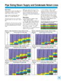
4 Note- Clean stem using soft cloth. DO NOT USE EMERY :Safety relief valve to be set at 10 psi higher or 10% higher than the downstream pressure, whichever is greater. The controller should be mounted such that steam does not come in direct contact with TrapSteamPython 1500 SeriesControl Valvewith PositionerAirSafetyReliefValveGate Valve12 Maintenance RequirementsUse by-pass valve or completely shut off the process to isolate the valve from process pressure. Drain fluid from both ends of the any operating lines providing air pressure, electric power or a Control signal to the :Avoid personal injury or damage to process system from sudden release of process fluid : Any gasket once removed should be replaced by a new one upon reassembly. This is necessary toensure a good joint :The valve plug must be off the seat while the coupling is being Removing Actuator from Valve Body (Figure 1)Put the actuator in the mid-lift position and secure it (by air or hand wheel).1 Unscrew the Allen bolts from coupling (15) and remove the two halves of stem gland nut (10) to allow the stem to slide free through the the air pressure and remove the air connection from the actuator4 Unscrew the slotted nut (14).
5 5 Lift the actuator assembly over the stem, off the valve, taking care to avoid damage to parts or accessories attached to the Body12 Seat13 Plug Spindle Dowel Bush17 Bottom Ring18 Gland Packing Set159 Gland Follower110 Gland Nut111 Bonnet Scews412 Bonnet Nut413 Yoke114 Slotted Nut115 Coupling116 Actuator1(Figure 1)B. Changing Valves (without hand wheel) from reverse acting (fail closed) to direct acting (fail open)DisassemblyClamp the actuator assembly in the all the screws (17) in the following order: a. Loosen all 8 screws except long screws. b. Loosen the long screws slowly to release pre-compression of the springs. c. Once the pre-compression is released, remove the screws. 2 Remove the upper casing (16).3 Remove the springs (8).4 Remove the stem-diaphragm assembly (9,10,11,12,13,14 &15).5 Perform the following steps to dismantle the stem-diaphragm assembly. a. Hold stem (9) at across flat in vice (soft jaws). b. Unscrew nut (15). c. Remove washer (14).
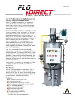
6 D. Remove spacer bush (10). e. Remove spring plate (11). f. Remove diaphragm plate (12). g. Remove diaphragm (13).66 Part Bush13O-Ring14Du Bush with Collar15O-Ring16 Lower Casing17 Yoke Nuts18 Springs49 Stem610 Spacer Bush111 Spring Plate112 Diaphragm Plate113 Diaphragm114 Washer115 Diaphragm Nut116 Upper Casing117 Screws With Nuts10(Figure 2)Perform the following steps to assemble the direct acting actuator a. Hold the yoke along with the lower casing fitted on a vice b. Place the actuator stem (9) in position c. Insert the spacer bush(10) on top of the actuator steam (9) d. Place all the six springs (8) in position on the lower casing (6). e. Install spring plate (11). f. Install diaphragm plate (12). g. Install diaphragm (13). h. Install washer (14). i. Lifting the actuator stem Screw diaphragm nut (15) using lock tight thread sealing solution on : Do not over tighten diaphragm nut (15). It may damage / extrude upper casing (16).
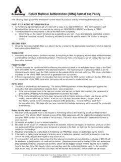
7 2 Screw all the screws (17) in the following order: a. Install the long screws tighten evenly to pre-compress springs b. Install remaining screws and use cross pattern for tightening to ensure even vent plug and place it in the air connection hole in the lower casing (6). The open hole in the upper casing is now the air inlet Bush13O-Ring14Du Bush with Collar15O-Ring16 Lower Casing17 Yoke Nuts18 Springs49 Stem610 Spacer Bush111 Spring Plate112 Diaphragm Plate113 Diaphragm114 Washer115 Diaphragm Nut116 Upper Casing117 Screws With Nuts10(Figure 3)C. Changing Valves (without hand wheel) from direct acting (fail open) to reverse acting (fail closed)Disassembly (Figure 3)Clamp the actuator assembly in the all the screws (17) in the following order: a. Loosen all screws except long screws. b. Loosen the long screws evenly to release the pre-compression of the springs. c. Once the pre-compression is released, remove the screws. 2 Remove upper casing (16).3 Remove stem-diaphragm assembly (9, 10, 11,12,13,14 & 15).
8 4 Perform following steps to dismantle the stem-diaphragm assembly. a. Hold stem (9) at across flat in vice (soft jaws) b. Unscrew diaphragm nut (15). c. Remove washer (14). d. Remove diaphragm (13). e. Remove diaphragm plate (12). f. Remove spring plate (11). g. Remove spacer bush (10).5 Remove springs (8).6 Assembly (Figure 2)Perform the following steps to assemble the stem-diaphragm assembly. a. Hold stem at across flat in vice (Soft jaws) b. Install diaphragm on stem (13). c. Install diaphragm plate (12). d. Install spring plate (11). e. Install spacer bush (10). f. Install washer (14). g. Screw diaphragm nut (15) using locktight thread sealing solution on : Do not overtighten diaphragm nut (15). It may damage / extrude stem-diaphragm assembly (9, 10, 11,12,13,14 &15).2 Install springs (8).3 Install upper casing (16).4 Screw all the screws (17) in the following order: a. Install the long screws tighten evenly to pre-compress springs.
9 B. Install remaining screws and use cross pattern for tightening to ensure even vent plug and place it in the air connection hole in the upper casing (16). The open hole in the lower casing is now the air inlet Diaphragm, O ring and DU bush Replacement Reverse Acting Actuator without hand wheel (Fail Closed) Figure 2 Hold the actuator in the all the screws (17) in the following order: a. Loosen all 8 screws except long screws. b. Loosen the long screws slowly to release pre-compression of the springs. c. Once the pre-compression is released, remove the screws. 2 Remove the upper casing (16).3 Remove the springs (8).4 Remove the stem-diaphragm assembly (9, 10, 11,12,13,14 &15).5O-ring and DU bush replacement- Unscrew yoke nut (7) to separate yoke (1) and lower casing (6) Remove O-ring (3), O ring (5), DU bush (2 and 4) from actuator yoke Replace with new parts. Do not use tool with sharp point or edge to insert new O ring. Sharp point or edge of the tool may damage / cut the O ring.
10 Apply grease to O replacement- Perform the following steps to dismantle the stem-diaphragm assembly. a. Hold stem (9) at across flat in vice (soft jaws). b. Unscrew diaphragm nut (15). c. Remove washer (14). d. Remove spacer bush (10). e. Remove spring plate (11). f. Remove diaphragm plate(12). g. Remove diaphragm(13). Install new diaphragm and assemble the actuator as described in Section B of the tightening the casings together, use a cross pattern for even Diaphragm, O ring and DU bush Replacement Direct Acting Actuator without hand wheel (Fail Open) Figure 3 Hold the actuator in the all the screws (17) in the following order: a. Loosen all screws except long screws. b. Loosen the long screws evenly to release the pre-compression of the springs. c. Once the pre-compression is released, remove the screws. 2 Remove the upper casing (16).3 Remove stem-diaphragm assembly (9, 10, 11,12,13,14 &15).4 Remove the springs5O-ring and DU bush replacement- Unscrew yoke nut (7) to separate yoke (1) and lower casing (6) Remove O-ring (3), O ring (5) and DU bush (2 and 4) from actuator yoke Replace with new parts.