Transcription of DATA SHEET - CITIZEN
1 04/15 DATA SHEETI ntroductionPerformance CharacteristicsMechanical DimensionsCharacteristic CurvesReliabilityPacking SpecificationPrecautionP 2P 3P 5P 6P 9P 10P 11 CITILED COB SeriesStandard 04/151. Introduction1-1. Product Description1-2. Features CITIZEN ELECTRONICS is the first COB manufacture. Our advanced knowledge and packaging technology for manyyears has excellent reliability and high quality of our products. CITILED COB Series covers a wide range of luminous fluxfrom a 10W incandescent bulb to a 300W mercury lamp in general lighting sources. The element arrangement of LEDpackage is capable of utilizing light more effectively and higher performance. The new version of CITILED COB series increase the performance significantly from previous version.
2 New versioncreates more options to match luminaire's products design (ex. High performance , Cost effective , Small Light EmittingSurface(LES), Increased allowable max. If). Emitted light density of the LED package is improved higher for suitable use oflight-condensing products. The outline and LES size is the same as for previous version. Thus existing parts of 3rdparties are compatible in mechanical characteristics. All of specs are at hot binning (Tj=85 C).2 Mechanical Dimensions : (mm) Package Structure: Aluminum Base Chip on Board Reference Assembly: M3 screw, Connector CRI (Ra): 80 Min., 70 Min. Nominal CCT: 2,700K, 3,000K, 3,500K, 4,000K, 5,000K ,6,500K ( CRI(Ra) 80 Min. )3,000K, 4,000K, 5,000K ( CRI(Ra) 70 Min.)
3 Chromaticity Range: 3-step MacAdam Ellipse, the center refers to ANSI :2011. ( CRI(Ra) 80 Min. )ANSI :2011. compliant ( CRI(Ra) 70 Min. ) Thermal Resistance: Maximum drive current : 460mA RoHS compliant Better die arrangement for optics Wide range of luminous flux and high efficacy Improved lumen density compared with previous versionCLU026 - 12 02 C1 - 27 3 M2 G2[1][2] [3][4][5][1][2][3][4][5]Product NomenclatureCRI (Ra) shapeDie count in seriesDie count in parallelNominal 04/152. Performance Characteristics2-1. Electro Optical Characteristics2-2. Absolute Maximum *1If460*1If min10Ir1 Top-40 ~ +100 Tst-40 ~ +100Tc105*2Tj140*3 Absolute Maximum Ratings*1. Input power and forward current are the values when the LED is used within the range of the deratingcurve in this data SHEET .
4 *2. Refer to 3. Outline drawing for Tc measurement Power (W)Forward Current (mA)Minimum Current (mA)Reverse Current (mA)*3. Current : Tj = Tc + Rj-c PiStorage Temperature (C)Case Temperature (C)Junction Temperature (C)Operating Temperature (C)3( Tj=85C )RaR9Tc=25C*Min. Min. Min. Typ. Typ. 836913134180 875955140180 894976143180 905988145180 918 1,002147180 936 1,022150180 945 1,032152180 977 1,067157180 991 1,082159180 :1. CITIZEN Electronics maintains forward voltage +/-3%, luminous flux +/-10%,Ra and R9 +/-1.*Values of Luminous flux at Tc=25C are provided as reference codeForwardCurrent( mA )ThermalResistanceRj-c( C/W )CRIN ominalCCTL uminous flux ( lm )Efficacy( lm/W )Voltage( V )T = 04/152-3.
5 Chromaticity CharacteristicsNote : CITIZEN Electronics maintains chromaticity ( x, y ) + chart CIE19314,000K3,500K3,000K2,700K5,000 KBlack Body Locus6,500 KANSI3-step42700K( , )3000K( , )3500K( , )4000K( , )5000K( , )6500K( , )3000K( , )4000K( , )5000K( , ) ( Rated current, Tj=85C )Color RegionNominalCCTC enter Point( x, y )Oval parameterMajor AxisaMinor AxisbEllipseRotation Angle 3-step MacAdam RegionNominalCCTC enter Point( x, y )ANSI parametera( x, y )b( x, y )c( x, y )d( x, y ) * Color region stay within MacAdam 3-step ellipse from the chromaticity center.* The chromaticity center refers to ANSI :2011. Please refer to ANSI C78.
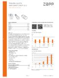
6 377 for the chromaticity center.* is the angle between the major axis of the ellipse and the x-axis, and a and b are the major and minor semi-axes of an ellipse.(Ref. IEC 60081:1997 AnnexD) C78. 377 04/153. Mechanical Dimensions5 Marking 1 : Serial 2 : CRICCTDies count in parallelDies count in series C 12 02 ** ** 04/15 Forward Current vs. Forward VoltageForward Current vs. Relative Luminous FluxTc=25 CTc=25 CCase Temperature vs. Forward VoltageCase Temperature vs. Relative Luminous FluxIf=180mAIf= [V]If [mA]0%50%100%150%200%250%0200400600 Relative Luminous Flux [ ]If [mA] [V]Tc [C]0%20%40%60%80%100%120%0255075100 Relative Luminous Flux [ ]Tc [C]4. Characteristic Curves4-1. Forward Current Characteristics / Temperature 04/15 Spectrum : CRI(Ra) 70 Min.
7 Tj=85 CIf=180mA0%10%20%30%40%50%60%70%80%90%10 0%380430480530580630680730780 Radiative Intensity Wave length [nm]5000K4000K3000 KSpectrum : CRI(Ra) 80 Min. Tj=85 CIf=180mA0%10%20%30%40%50%60%70%80%90%10 0%380430480530580630680730780 Radiative Intensity Wave length [nm]6500K5000K4000K3500K3000K2700K4-2. Optical 04/15 Radiation Characteristic0%20%40%60%80%100%XY80 70 60 50 40 30 20 10 -80 -70 -60 -50 -20 -30 -40 -10 90 -90 Case Temperature vs. Allowable Forward Current050100150200250300350400450500025 50 75 100 125If [mA]Tc [C]4-2. Optical Characteristics (continued)4-3. Derating 04/155. Reliability5-1. Reliability Test5-2. Failure Criteria -40 C 30 minutes 100 C 30 minutes, 100 cycle 85 C, 85 %RH for 500 hoursThermal Shock TestContinuous Operation TestHigh Temperature Storage TestLow Temperature Storage TestMoisture-proof TestIF=180mA Tj=140C (with Al-fin) 1000hrsTest Item 100 C 1000 hours -40 C 1000 hoursTest ConditionIF=180mA Ta=25C (with Al-fin) 1000hrs9( Tc=25C )U defines the upper limit of the specified characteristics.
8 S defines the initial : Measurement shall be taken between 2 hours and 24 hours, and the test pieces should be return to the normal ambient conditions after the completion of each Luminous Flux vIf=180mA<S ItemSymbolMeasuring ConditionFailure CriteriaForward VoltageVfIf=180mA>U 04/151 5 5 5 0 0 1(2)(1)(3)Example of indication label1. TYPE CLU026-1202C12. ( Cutomer's P/N ) 3. Lot No. 4. Quantity (1) Last two digit of the year 15 : year 2015(2) Production month5 : May Note: October, November and December are designated X,Y and Z.(3) CE's control number 6. Packing Specification6-1. Packing10An empty tray is placed on top of a 6-tier tray which contain 54 pieces each.
9 (Smallest packing unit: 324 pieces) A label with product name, quantity and lot number is placed on the upper empty (Dimensions: 310 x 210 x 12 mm / Materials: Electrically conductive PS) NoQ'ty: CLU**-**-**: **: **: **--- ( 1 )--- ( 2 )--- ( 3 )--- ( 4 ) 04/157. Precaution7-1. Handling with care for this product-Both the light emitting area and white rim around the light emitting area is composed of resin materials. Please avoid the resin area from being pressed, stressed, rubbed, come into contact with sharp metal nail ( edge of reflector part) because the function, performance and reliability of this product are negatively be aware that this product should not come into contact with any other parts while incorporating in your lighting apparatus or your other be aware that careful handling is required after the attachment of lead wires to prevent the application of any load to the more information, please refer to application note "Instruction Manual(COB LED Package)".
10 7-2. Countermeasure against static electricity-Handling of this product needs countermeasures against static electricity because this is a semiconductor product. -Please take adequate measures to prevent any static electricity being produced such as the wearing of a wristband or anti-static gloves when handling this manufacturing facility in regard to the product (plant, equipment, machine, carrier machine and conveyance unit) should be connected to ground and please avoid the product to be sensitivity of this product is over 1000V (HBM, based on JEITA ED-4701/304).-After assembling the LEDs into your final product(s), it is recommended to check whether the assembled LEDs are damaged by static electricity (electrical leak phenomenon) or is easy to find static damaged LED dies by a light-on test with the minimum current Caution of product assembly-Regarding this product assembling on the heat sink, it is recommended to use M3 screw.