Transcription of Data Sheet No. PD94173 revD IRU3037/IRU3037A …
1 IRU3037/IRU3037A & (PbF) APPLICATIONDESCRIPTIONThe iru3037 controller IC is designed to provide a lowcost synchronous Buck regulator for on-board DC to DCconverter applications. With the migration of today s ASIC products requiring low supply voltages such as andlower, together with currents in excess of 3A, traditionallinear regulators are simply too lossy to be used wheninput supply is 5V or even in some cases with supply. The iru3037 together with dual N-channelMOSFETs such as IRF7313, provide a low cost solutionfor such applications. This device features an internal200 KHz oscillator (400 KHz for "A" version), under-volt-age lockout for both Vcc and Vc supplies, an externalprogrammable soft-start function as well as output un-der-voltage detection that latches off the device when anoutput short is controller in 8-Pin PackageOperating with single 5V or 12V supply voltageInternal 200 KHz Oscillator(400 KHz for iru3037a )Soft-Start FunctionFixed Frequency Voltage Mode500mA Peak Output Drive CapabilityProtects the output when control FET is shortedSOIC 8-Lead also available LEAD-FREEPACKAGE ORDER INFORMATIONFEATURES 8-PIN SYNCHRONOUS PWM CONTROLLERAPPLICATIONSDDR memory source sink Vtt applicationLow cost on-board DC to DC such as 5V to , or CardHard Disk DriveData Sheet No.
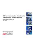
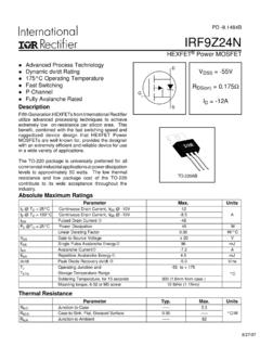
2 PD94173 revDFigure 1 - Typical application of iru3037 or of IRF7313Q21/2 of , 1%R3249, 1%L2D05022P-562, , , 100uF, 55m 6 TPC150M,150uF, 40m 12V5 VTA ( C) DEVICE LEADFREE DEVICE PACKAGE FREQUENCY0 To 70 IRU3037CF iru3037 CFPbF8-Pin Plastic TSSOP (F)200 KHz0 To 70 IRU3037CS iru3037 CSPbF8-Pin Plastic SOIC NB (S)200 KHz0 To 70 iru3037 ACF iru3037 ACFPbF8-Pin Plastic TSSOP (F)400 KHz0 To 70 iru3037 ACS iru3037 ACSPbF8-Pin Plastic SOIC NB (S)400 KHz2 IRU3037/IRU3037A & (PbF) MAXIMUM RATINGSVcc Supply Voltage .. 25 VVc Supply Voltage .. 30V (not rated for inductive load)Storage Temperature Range .. -65 C To 150 COperating Junction Temperature Range .. 0 C To 125 CCAUTION: Stresses above those listed in "Absolute Maximum Ratings" may cause permanent damage to the SYM TEST CONDITION MIN TYP MAX UNITSR eference VoltageFb VoltageFb Voltage Line RegulationUVLOUVLO Threshold - VccUVLO Hysteresis - VccUVLO Threshold - VcUVLO Hysteresis - VcUVLO Threshold - FbUVLO Hysteresis - FbSupply CurrentVcc Dynamic Supply CurrentVc Dynamic Supply CurrentVcc Static Supply CurrentVc Static Supply CurrentSoft-Start SectionCharge CurrentIRU3037 IRU3037A5<Vcc<12 Supply Ramping UpSupply Ramping UpFb Ramping Down ( iru3037 ) ( iru3037a )Freq=200 KHz, CL=1500pFFreq=200 KHz, CL=1500pFSS=0 VSS=0 VSS= AVFBLREGUVLO VccUVLO VcUVLO FbDyn IccDyn IcICCQICQSSIB JA=160 C/W(Also available LEAD-FREE)
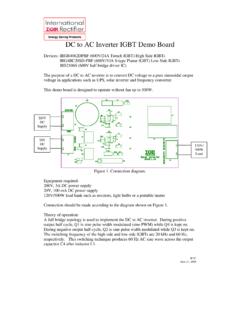
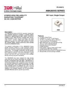
3 JA=124 C/WFbVccLDrvGndHDrvVcCompSS/SD43215678 FbVccLDrvGndSS/SDCompVcHDrv43215678 ELECTRICAL SPECIFICATIONSU nless otherwise specified, these specifications apply over Vcc=5V, Vc=12V and TA=0 to 70 C. Typical values referto TA=25 C. Low duty cycle pulse testing is used which keeps junction and case temperatures equal to the INFORMATION 8-PIN PLASTIC TSSOP (F) 8-PIN PLASTIC SOIC (S) IRU3037/IRU3037A & (PbF) SYM TEST CONDITION MIN TYP MAX UNITSPIN DESCRIPTIONSThis pin is connected directly to the output of the switching regulator via resistor divider toprovide feedback to the Error pin provides biasing for the internal blocks of the IC as well as power for the low sidedriver. A minimum of 1 F, high frequency capacitor must be connected from this pin toground to provide peak drive current driver for the synchronous power pin serves as the ground pin and must be connected directly to the ground plane.
4 Ahigh frequency capacitor ( to 1 F) must be connected from V5 and V12 pins to this pinfor noise free driver for the high side power MOSFET. Connect a diode, such as BAT54 or 1N4148,from this pin to ground for the application when the inductor current goes negative (Source/Sink), soft-start at no load and for the fast load transient from full load to no pin is connected to a voltage that must be at least 4V higher than the bus voltage ofthe switcher (assuming 5V threshold MOSFET) and powers the high side output driver. Aminimum of 1 F, high frequency capacitor must be connected from this pin to ground toprovide peak drive current pin of the error amplifier. An external resistor and capacitor network istypically connected from this pin to ground to provide loop pin provides soft-start for the switching regulator. An internal current source chargesan external capacitor that is connected from this pin to ground which ramps up the outputof the switching regulator, preventing it from overshooting as well as limiting the inputcurrent.
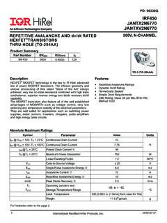
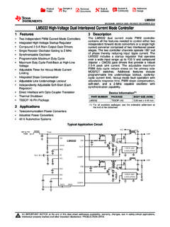
5 The converter can be shutdown by pulling this pin below AmpFb Voltage Input Bias CurrentFb Voltage Input Bias CurrentTransconductanceOscillatorFrequen cyRamp-Amplitude VoltageOutput DriversRise TimeFall TimeDead Band TimeMax Duty CycleMin Duty CycleSS=3V, Fb=1 VSS=0V, Fb=1 VIRU3037 iru3037 ACL=1500pFCL=1500pFFb=1V, Freq=200 KHzFb= A A mhoKHzVnsnsns%%PIN# PIN SYMBOL PIN DESCRIPTION12345678 FbVccLDrvGndHDrvVcCompSS / SDIFB1 IFB2gmFreqVRAMPTrTfTDBTONTOFF4 IRU3037/IRU3037A & (PbF) DIAGRAMF igure 2 - Simplified block diagram of the OF OPERATIONI ntroductionThe iru3037 is a fixed frequency, voltage mode syn-chronous controller and consists of a precision refer-ence voltage, an error amplifier, an internal oscillator, aPWM comparator, peak gate driver, soft-start andshutdown circuits (see Block Diagram).The output voltage of the synchronous converter is setand controlled by the output of the error amplifier; this isthe amplified error signal from the sensed output voltageand the reference voltage is compared to a fixed frequency linearsawtooth ramp and generates fixed frequency pulses ofvariable duty-cycle, which drives the two N-channel ex-ternal timing of the IC is provided throughan internal oscillator circuit which uses on-chip capaci-tor to set the oscillation frequency to 200 KHz (400 KHzfor A version).
6 Soft-StartThe iru3037 has a programmable soft-start to controlthe output voltage rise and limit the current surge at thestart-up. To ensure correct start-up, the soft-start se-quence initiates when the Vc and Vcc rise above theirthreshold ( and respectively) and generatesthe Power On Reset (POR) signal. Soft-start functionoperates by sourcing an internal current to charge anexternal capacitor to about 3V. Initially, the soft-start func-tion clamps the E/A s output of the PWM converter. Asthe charging voltage of the external capacitor ramps up,the PWM signals increase from zero to the point thefeedback loop takes ProtectionThe outputs are protected against the short-circuit. TheIRU3037 protects the circuit for shorted output by sens-ing the output voltage (through the external resistor di-vider). The iru3037 shuts down the PWM signals, whenthe output voltage drops below ( for iru3037a ).
7 The iru3037 also protects the output from over-voltagingwhen the control FET is shorted. This is done by turningon the sync FET with the maximum duty LockoutThe under-voltage lockout circuit assures that theMOSFET driver outputs remain in the off state wheneverthe supply voltage drops below set parameters. Lockoutoccurs if Vc or Vcc fall below and respec-tively. Normal operation resumes once Vc and Vcc riseabove the set MaxPORO scillatorError AmpCtError CompReset & (PbF) 3 - Typical application of the iru3037 forprogramming the output INFORMATIOND esign Example:The following example is a typical application for iru3037 ,the schematic is Figure 18 on page Voltage ProgrammingOutput voltage is programmed by reference voltage andexternal voltage divider. The Fb pin is the inverting inputof the error amplifier, which is internally referenced ( for iru3037a ). The divider is ratioed to pro-vide at the Fb pin when the output is at its desiredvalue.
8 The output voltage is defined by using the follow-ing equation:When an external resistor divider is connected to theoutput as shown in Figure (1) can be rewritten as:Choose R5 = 1K This will result to R6 = If the high value feedback resistors are used, the inputbias current of the Fb pin could cause a slight increasein output voltage. The output voltage set point can bemore accurate by using precision ProgrammingThe soft-start timing can be programmed by selectingthe soft start capacitance value. The start up time of theconverter can be calculated by using:Where:CSS is the soft-start capacitor ( F)For a start-up time of , the soft-start capacitor willbe F. Choose a ceramic capacitor at converter can be shutdown by pulling the soft-startpin below The control MOSFET turns off and thesynchronous MOSFET turns on during Supply VcTo drive the high-side switch it is necessary to supply agate voltage at least 4V greater than the bus is achieved by using a charge pump configurationas shown in Figure 18.
9 The capacitor is charged up toapproximately twice the bus voltage. A capacitor in therange of F to 1 F is generally adequate for mostapplications. In application, when a separate voltagesource is available the boost circuit can be avoided asshown in Figure Capacitor SelectionThe input filter capacitor should be based on how muchripple the supply can tolerate on the DC input line. Thelarger capacitor, the less ripple expected but considershould be taken for the higher surge current during thepower-up. The iru3037 provides the soft-start functionwhich controls and limits the current surge. The value ofthe input capacitor can be calculated by the followingformula:Where:CIN is the input capacitance ( F)IIN is the input current (A) t is the turn on time of the high-side switch ( s) V is the allowable peak to peak voltage ripple (V)FbIRU3037 VOUTR5R6tSTART = 75 Css (ms) ---(2)VIN = 5 VVOUT = = 4A VOUT = 100mVfS = 200 KHzR6 = R5 - 1 VOUTVREF( )VOUT = VREF 1 + ---(1)R6R5( )CIN = ---(3)IIN t V6 IRU3037/IRU3037A & (PbF) the following:By using equation (3), CIN = FFor higher efficiency, low ESR capacitor is two 100 F Sanyo TPB series PosCap capacitor 100 F, 10 Vwith 55m ESR is a good Capacitor SelectionThe criteria to select the output capacitor is normallybased on the value of the Effective Series Resistance(ESR).
10 In general, the output capacitor must have lowenough ESR to meet output ripple and load transientrequirements, yet have high enough ESR to satisfy sta-bility requirements. The ESR of the output capacitor iscalculated by the following relationship:The Sanyo TPC series, PosCap capacitor is a goodchoice. The 6 TPC150M 150 F, has an ESR 40m .Selecting two of these capacitors in parallel, results toan ESR of 20m which achieves our low ESR capacitor value must be high enough to absorb theinductor's ripple current. The larger the value of capaci-tor, the lower will be the output ripple SelectionThe inductor is selected based on output power, operat-ing frequency and efficiency requirements. Low inductorvalue causes large ripple current, resulting in the smallersize, but poor efficiency and high output noise. Gener-ally, the selection of inductor value can be reduced todesired maximum ripple current in the inductor ( i).