Transcription of Irf9z24n - Infineon Technologies
1 IRF9Z24 NHEXFET Power MOSFETPD Generation HEXFETs from International Rectifierutilize advanced processing techniques to achieveextremely low on-resistance per silicon area. Thisbenefit, combined with the fast switching speed andruggedized device design that HEXFET PowerMOSFETs are well known for, provides the designerwith an extremely efficient and reliable device for usein a wide variety of TO-220 package is universally preferred for allcommercial-industrial applications at power dissipationlevels to approximately 50 watts. The low thermalresistance and low package cost of the TO-220contribute to its wide acceptance throughout @ TC = 25 CContinuous Drain current , VGS @ -10V-12ID @ TC = 100 CContinuous Drain current , VGS @ Drain current -48PD @TC = 25 CPower Dissipation45 WLinear Derating CVGSGate-to-Source Voltage 20 VEASS ingle Pulse Avalanche Energy 96mJIARA valanche current Avalanche Energy Diode Recovery dv/dt Junction and-55 to + 175 TSTGS torage Temperature RangeSoldering Temperature, for 10 seconds300 ( from case ) CMounting torque, 6-32 or M3 screw10 lbf in ( m)Absolute Maximum JCJunction-to-Case CSCase-to-Sink, Flat, Greased C/WR JAJunction-to-Ambient 62 Thermal ResistanceVDSS = -55 VRDS(on)
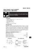
2 = ID = -12 ATO-220 ABlAdvanced Process TechnologylDynamic dv/dt Ratingl175 C Operating TemperaturelFast SwitchinglP-ChannellFully Avalanche RatedDescription8/27/97 SDGIRF9Z24N Units ConditionsISContinuous Source CurrentMOSFET symbol(Body Diode) showing theISMP ulsed Source Currentintegral reverse(Body Diode) p-n junction Forward Voltage = 25 C, IS = , VGS = 0V trrReverse Recovery Time 4771nsTJ = 25 C, IF = RecoveryCharge 84130 Cdi/dt = -100A/ s tonForward Turn-On TimeIntrinsic turn-on time is negligible (turn-on is dominated by LS+LD) Units ConditionsV(BR)DSSD rain-to-Source Breakdown Voltage-55 VVGS = 0V, ID = -250 A V(BR)DSS/ TJBreakdown Voltage Temp. Coefficient V/ C Reference to 25 C, ID = -1mARDS(on)Static Drain-to-Source On-Resistance VGS = -10V, ID = VGS(th)Gate Threshold = VGS, ID = -250 AgfsForward SVDS = -25V, ID = -25 AVDS = -55V, VGS = 0V -250 VDS = -44V, VGS = 0V, TJ = 150 CGate-to-Source Forward Leakage 100 VGS = 20 VGate-to-Source Reverse Leakage -100nAVGS = -20 VQgTotal Gate Charge 19ID = Charge = -44 VQgdGate-to-Drain ("Miller") Charge 10 VGS = -10V, See Fig.
3 6 and 13 td(on)Turn-On Delay Time 13 VDD = -28 VtrRise Time 55 ID = (off)Turn-Off Delay Time 23 RG = 24 tfFall Time 37 RD = , See Fig. 10 Between lead, 6mm ( )from packageand center of die contactCissInput Capacitance 350 VGS = 0 VCossOutput Capacitance 170 pFVDS = -25 VCrssReverse Transfer Capacitance 92 = , See Fig. 5nHElectrical Characteristics @ TJ = 25 C (unless otherwise specified)LDInternal Drain InductanceLSInternal Source Inductance Leakage current Repetitive rating; pulse width limited by max. junction temperature. ( See fig. 11 ) ISD , di/dt -280A/ s, VDD V(BR)DSS, TJ 175 CNotes: Starting TJ = 25 C, L = RG = 25 , IAS = (See Figure 12) Pulse width 300 s; duty cycle 2%.SDGS ource-Drain Ratings and CharacteristicsASDG-12-48 IRF9Z24 NFig 4.
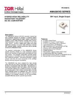
4 Normalized On-ResistanceVs. TemperatureFig 2. Typical Output Characteristics,Fig 1. Typical Output Characteristics,Fig 3. Typical Transfer 20 s PULSE WIDTH T = 25 CA-I , Drain-to-S ource current (A)-V , Drain-to-Source Voltage (V) VGS TOP - 15V - 10V - - - - - BO TT OM - 4. 5V , Drain-to-Source current (A)-V , Drain-to-Source Voltage (V) VGS TOP - 15V - 10V - - - - - BO TT OM - 4. V 20 s PULSE WIDTH T = 175 CC11010045678910T = 25 CJGSDA-I , Dra in-to-So urc e C urre nt (A )-V , Ga te-to-So urce Voltage (V) V = -2 5 V 20 s PULSE W IDTH DST = 175 -40 -20020406080100 120 140 160 180JT , Junction Temperature ( C)R , D rain -to -S ourc e O n R e sistan ceDS(on)(Norm alized)A V = -10 V GS I = -12 ADJJIRF9Z24 NFig 8.
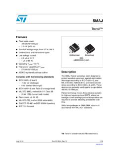
5 Maximum Safe Operating AreaFig 6. Typical Gate Charge VoltageFig 5. Typical Capacitance VoltageFig 7. Typical Source-Drain DiodeForward Voltage0481216200510152025 GGSA-V , G ate-to-S ource V oltage (V )Q , Total Gate Charge (nC) FOR TEST CIRCUIT SEE FIGURE 13 I = A V = -4 4V V = -2 = 25 CT = 150 CJJV = 0 V GSSDSDA-I , R eve rse D ra in current (A)-V , Source-to-Drain Voltage (V)110100110100 OPERATION IN THIS AREA LIMITED BY RDS(on)10m sA-I , D rain C urre nt (A)-V , Drain-to-Source Voltage (V)DSD1 0 s100 s1m s T = 2 5 C T = 1 75 C Single PulseCJ0100200300400500600700110100C, Capacitance (pF)DSV , Drain-to-Source V oltage (V)AV = 0V , f = 1MH zC = C + C , C SH OR TEDC = CC = C + CGSiss gs g d dsrss g doss ds gdC is sC ossC rs sIRF9Z24 NFig 10a.
6 Switching Time Test CircuitFig 10b. Switching Time WaveformsFig 11. Maximum Effective Transient Thermal Impedance, Junction-to-CaseFig 9. Maximum Drain current TemperatureVDS-10 VPulse Width 1 sDuty Factor % +-VDS90%10%VGStd(on)trtd(off)tf036912255 075100125150175CT , C ase Temperature ( C)A-I , D rain current (Am ps) , Rectangular Pulse Duration (sec)1th JCD = S IN G LE P U L S E(THERMAL RESPONSE)AThermal R esponse (Z )Pt21tDMNotes: 1. D uty factor D = t / t 2. Pea k T = P x Z + T 12 JDMth JCC IRF9Z24 NFig 13b. Gate Charge Test CircuitFig 13a. Basic Gate Charge WaveformFig 12c. Maximum Avalanche EnergyVs. Drain F50K .2 F12 VCurrent RegulatorSame Type as Sampling Resistors+-Fig 12b.
7 Unclamped Inductive WaveformsFig 12a. Unclamped Inductive Test CircuittpV(BR) , S ingle Pulse Avalanche E nergy (m J)ASAS tarting T , Junction Temperature ( C) ITO P AB OTTO M ADIRF9Z24 NPeak Diode Recovery dv/dt Test Recoverydv/dtRipple 5%Body Diode Forward DropRe-AppliedVoltageReverseRecoveryCurr entBody Diode ForwardCurrentVGS=10 VVDDISDD river Gate VDSW aveformInductor CurentD = P. W .Period+-+++--- RGVDD dv/dt controlled by RG ISD controlled by Duty Factor "D" - Device Under *Circuit Layout Considerations Low Stray Inductance Ground Plane Low Leakage Inductance current Transformer * Reverse Polarity of for P-ChannelVGS[ ][ ]** VGS = for Logic Level and 3V Drive Devices[ ] **Fig 14.
8 For P-Channel HEXFETSIRF9Z24 NLEAD ASSIGNMENTS 1 - G A T E 2 - D R AIN 3 - SO URCE 4 - D R AIN- B (.052) (.048) 5 (.02 2) 6 (.01 8) (.115) (.104) (.185) (.165) (.037) (.027) 6 (.16 0) 5 (.14 0) (.0 4 5) M 7 (.25 5) 0 (.24 0) (.14 9) (.13 9)- A -1 4 (.41 5)1 9 (.40 5) (.113) (.103) (.600) (.584) (.555) (.530) (.055) (.045) (.100)2X0 .3 6 (.01 4) M B A M41 2 3 NOTES: 1 D IM E N S IO N IN G & T O L ER AN C IN G P ER A N S I Y 14 .5 M , 1 98 2. 3 O U T L IN E C O N F O R M S T O JE D E C OU T LIN E T O -2 20 A B. 2 CO NTR OLLING D IMENSIO N : INCH 4 HEATSIN K & LEAD M EASUREMENTS D O NO T INCLUDE BU NUMBERIN TER NATION AL R EC TIFIER LO GOEXAMPLE : THIS IS AN IRF1010 W ITH ASSEMBLY LO T CO DE 9B1M ASSEMBLY LO T CO DEDATE CODE (YYWW)YY = YEARWW = WEEK9246 IRF10109B 1 MAPart Marking InformationTO-220 ABPackage OutlineTO-220AB OutlineDimensions are shown in millimeters (inches)PART NUMBERIN TER NATION AL R EC TIFIER LO GOEXAMPLE : THIS IS AN IRF1010 W ITH ASSEMBLY LO T CO DE 9B1M ASSEMBLY LO T CO DEDATE CODE (YYWW)YY = YEARWW = WEEK9246 IRF10109B 1 MAWORLD HEADQUARTERS: 233 Kansas St.
9 , El Segundo, California 90245, Tel: (310) 322 3331 EUROPEAN HEADQUARTERS: Hurst Green, Oxted, Surrey RH8 9BB, UK Tel: ++ 44 1883 732020IR CANADA: 7321 Victoria Park Ave., Suite 201, Markham, Ontario L3R 2Z8, Tel: (905) 475 1897IR GERMANY: Saalburgstrasse 157, 61350 Bad Homburg Tel: ++ 49 6172 96590IR ITALY: Via Liguria 49, 10071 Borgaro, Torino Tel: ++ 39 11 451 0111IR FAR EAST: K&H Bldg., 2F, 30-4 Nishi-Ikebukuro 3-Chome, Toshima-Ki, Tokyo Japan 171 Tel: 81 3 3983 0086IR SOUTHEAST ASIA: 315 Outram Road, #10-02 Tan Boon Liat Building, Singapore 0316 Tel: 65 221 8371 and specifications subject to change without : For the most current drawings please refer to the IR website at.