Transcription of Datasheet DIN Rail Mount - Crydom
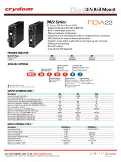
1 Do not forget to visit us at: 2017 Crydom Inc. Specifications subject to change without DR Series Ratings 3 Amps Load voltage ratings of 1-60 VDC, 1-100 VDC, 24-280 VAC and 48-600 VAC Fits standard 35mm DIN rail LED input status indicator AC or DC control Zero Voltage (resistive loads) or Instantaneous (inductive loads) turn-on output UL and cUL Listed, HP Rated CE & RoHS Compliant UL 508 Endurance Rating for Enhanced Reliability UL Class I and II, Division 2, for Hazardous LocationsPRODUCT SELECTIONC ontrol Voltage 280V, 3 A 600V, 3 A 60V, 3 A 100V, 3 A4-32 VDC DR10D0390-140 VAC200-280 VACAVAILABLE OPTIONSOUTPUT SPECIFICATIONS AC Output (2)DescriptionDR24x03DR48x03DR06D03DR10D 03 Operating Voltage (3)
2 24-280 Vrms48-600 Vrms1-60 VDC1-100 VDCT ransient Overvoltage [Vpk]6001200N/AN/AMaximum Load Current, resistive (4)3 Arms3 Arms33150 mArms150 Load Current 500500N/AN/AMaximum Surge Current (50/60Hz, 1 cycle) [Apk] On-State Voltage Drop @ Rated Current [Vpk] 285/300285/3006060410/375410/375N/AN/AMa ximum I t for Fusing (50/60 Hz, 1/2 cycle) [A sec]1/4 (.18)1/4 (.18)N/AN/AN/A1/3 (.25)N/AN/A18-36 VACDR24D03DR24B03DR24A03DR48D03DR06D03DR 24E03 Maximum Off-State Leakage Current @ Rated Voltage [mA]Minimum Off-State dv/dt @ Maximum Rated Voltage [V/ sec] (5) HP Rating UL 508/IEC60947 [HP (KW)] @ 240 VMinimum Power Factor (at Maximum Load)Min/Max stranded wireHP Rating UL 508/IEC60947 [HP (KW)] @ 380 VHP Rating UL 508/IEC60947 [HP (KW)] @ 480 VMin/Max solid wireWeight (Typical)N/AN/A1/2 (.)
3 37) AWG22/14 AWG22/14 AWG22/14 AWG22/14 AWG22/14 AWG22/14 AWG22/14 oz. (50g) oz. (50g) oz. (50g) oz. (50g)ACOutputOnlySeriesOperating Voltage06: 1-60 VDC10: 1-100 VDC24: 24-280 VAC48: 48-600 VACR ated Load Current03: 3 AmpsControl VoltageD: 4-32 VDCA: 200-265 VACB: 90-140 VACE: 18-36 VAC (1) 0306 DDRXA gency ApprovalsX: ATEX II 3G Ex nA IIC T4 Gc approvedSwitching TypeBlank: Zero Voltage Turn-On (AC Output Only)R: Instantaneous Turn-On (AC Output)RRequired for valid part numberFor options only and not required for valid part numberDCACD atasheetDIN rail MountDatasheetDIN rail MountINPUT SPECIFICATIONS(2)DRxxExxDRxxBxxDRxxDxxDe scriptionControl Voltage Range (6) 4-32 VDC200-265 Vrms18-36 Vrms (1) Min imum Tur n- On Vol VDC200 Vrms18 VrmsMust Turn-Off VDC40 Vrms4 VrmsMinimum Input Current for [mA] (7) Input Current for [mA] (8) Cycle20 msec20 msecMaximum Turn-on Time [msec] (8) (9)1/2 Cycle30 msec30 msecMaximum Turn-off Time [msec] (10)22/16 AWG22/16 AWG22/16 AWGGENERAL SPECIFICATIONS(2)
4 DescriptionParametersDielectric Strength, Input/Output/Base (50/60Hz)4000 Vrms (11) Minimum Insulation Resistance (@ 500 VDC)Maximum Capacitance, Input/Output10 pFAmbi ent Operating Temperature Range-30 to 80 CAmbi ent Storage Temperature Range-30 to 100 in-lb ( )Recommended Ter minal Scre w Torque Range 109 OhmMin/Max stranded/solid wireDRxxAxx90-140 Vrms90 Vrms10 Vrms3520 msec30 msec22/16 AWGGENERAL NOTES (2) All parameters at 25 C unless otherwise specified. (3) For AC output frequency is 47-63Hz (5) Off-State dv/dt test method per EIA/NARM standard RS-443, paragraph (6) DC control includes reverse polarity protection.
5 (7) Input circuitry incorporates active current limiter.(8) Turn-on time for DC control random turn-on versions is msec.(9) Turn-on time for DC output 600 sec.(10) Turn-off time for DC output 300 sec.(11) 2500 Vrms for DC A, Resistive or Slightly Inductive Load Ratings: 3A @40 C ambient for DR24x03, 3A @ 40 C ambient for DR48x03LC B, Motor Loads Ratings: @ 240 VAC for DR24x03 and @ 480 VAC DR48x13 Standards of Compliance IEC 62314 Shock and Vibration (Applies to all part numbers)Vibration Resistence according to IEC 60068-2-6: and Amplitude over 10-55 HzShock Resistance according to IEC 60068-2-27: 15g/11msEMC (Applies to all part numbers)IEC 61000-4-2: Electrostatic Discharge- Level 3 IEC 61000-4-4: Electrically Fast Transients- Level 3 IEC 61000-4-5.
6 Electrical Surges- Level 3 ANSI / ISA Electrical Equipment for Use in Class I and II, Division 2 and Class III, Division 1 and 2 Hazadous (classified) locationsThis equipment is open-type device and is meant to be installed in an enclosure suitable for the enviroment such that the equipment is only accesible with the use of a toolsuitable for use in Class 1, Division 2, Group A,B,C and Hazardous locations, or Nonhazardous locations onlyWARNING-Explosion Hazard- Do not disconnect equipment while the circuit is live or unless the area is known to be free of ignitable concentrationsWARNING-Explosion Hazard- Substitution of any component may impair suitability for class I, Division 2(4) See Derating curves (1)
7 E option is UL certified for AC control voltage, but it works also with 18-36 VDC input range. Do not forget to visit us at: 2017 Crydom Inc. Specifications subject to change without not forget to visit us at: 2017 Crydom Inc. Specifications subject to change without rail MountMECHANICAL SPECIFICATIONS(2)EQUIVALENT CIRCUIT BLOCK DIAGRAMS/WIRING DIAGRAMSACACACT riggerCircuitACAABBAC/DCConverter-DC+DC+ ACTriggerCircuitACVisibleLEDV isibleLEDLOADLOAD+3/A1 3/A1-4/A1-4/A12/T11/L1 LOADLOAD2/T11/L1AB-VDC+VDCLOADLOAD2/T11/ L1 CurrentLimiter-DC+DC+3/A1-4/A1 ControlCircuitLoad can be wired in position A or B(A) Load can be wired in position A or B(A) (A) (A) (B) (B) Inductive loads must be diode supressed to prevent damage to SSRD atasheetDIN rail MountDo not forget to visit us at: 2017 Crydom Inc.
8 Specifications subject to change without DERATE INFORMATION Rev 02227321100203040506070800 Ambient Temperature ( C)Load Current (Amps)DRxxx03 Single and multiple unitsAGENCY APPROVALSE116949 IND. CONT. rail MountDo not forget to visit us at: 2017 Crydom Inc. Specifications subject to change without rail MountACCESORIESDo not forget to visit us at: 2017 Crydom Inc. Specifications subject to change without rail MountDANGER / PELIGRO / DANGER /GEFAHR / PERICOLO / HAZARD OF ELECTRIC SHOCK, EXPLOSIO N, OR ARC FLASH. Di sconnect all power b efore insta lling or working with th is equipment.
9 Verify all connecti ons and r eplace a ll covers b efore tu rning o n t o f ollow these in structio ns will result in d eath or s erio us inju ry. RIESGO DE DESCARGA ELECTRICA O EXPLOSIO N. Desconecta r to dos los suministr os d e energia a e ste equipo antes de tr abajar con e ste equipo. Verificar todas las conexiones y colocar todas las tapas antes de energizer el in cumplimie nto de e stas in struccio nes puede p rovocar la muerte o le sio nes s eria DE DESCHARGE ELECTRIQUE OU EXPLOSION Ete indre to ute s les sources d' nergie de cet a ppareil avant de tr availler dessus d e c et appareil V rifier tousconnections, etremettre tous couverts enolace avant demettre sousDe n on-suiv i de ces instructio ns provoquera la mort o u d es l sio ns s rieuses s EIN ES ELEKTRISCHEN SCHLAGES ODER EINER EXPLOSIO N.
10 Ste llen Sie jeglichen Str om a b, d er dieses G er t versorgt, bevor S ie an dem Ger t Arbeiten durchf hren Vor d em Dr ehen auf Energie alle Anschl sse berpr fen und alle Abdeckungen ssung die ser Anweisungen k nnen z um Tode o der z u schwerenVerle tzungen f DI SCOSSA ELETTRICA O DELL E SPLOSIONE. Spenga tu tt a l'alimenta zioneche f ornisce questa apparecchiaturaprima d i lavorarea questa apparecchiatura Verificare t utti i c ollegamenti e s osti tu ire tu tte le coperture prima dell accensioneL'omis sio ne d i queste istruzioni provocher l a morte ole sio ni serie WARNING / AVERTISSEMENT / WARNUNG /ADVERTENCIA / AVVERTENZA / RISK OF MATERIAL DAMAGE AND HOT ENCLOSURE The product's side panels may be hot, allow the product to cool before touching.