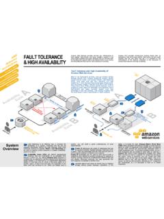
Transcription of Datasheet Panel Mount - Crydom
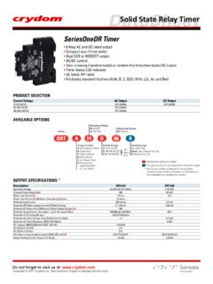
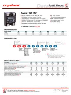
1 Datasheet Panel Mount HA / HD48 Series Ratings from 12A to 125A @ 48-530 VAC AC or DC control SCR output for heavy industrial loads Direct bond copper substrate Zero Voltage or instantaneous turn-on outputs EMC compliant to Level 3. UL/CSA/VDE Approved, CE Compliant to EN60950-1 Direct power lead frame Improved SEMS screw and washer Epoxy free design Redesigned housing with anti-rotation barriers For Generation 3 Datasheet click here PRODUCT SELECTION. Control Voltage 12A 25A 50A 75A 90A 110A 125A. 4-32 VDC HD4812 HD4825 HD4850 HD4875 HD4890 HD48110 HD48125. 90-280 Vrms HA4812 HA4825 HA4850 HA4875 HA4890 HA48110 HA48125. 18-36 Vrms HA4812E HA4825E HA4850E HA4875E HA4890E HA48110E HA48125E. AVAILABLE OPTIONS. Control Voltage A: 90-280 VAC Overvoltage Protection Snubber Switching Type D: 4-32 VDC Blank: Not Included Blank: Not Included Blank: Zero Voltage Turn-On Series AxxxxE: 18-36 VAC P: Included (3) S: Included -10: Instantaneous Turn-On (4).
2 H A 48 25 E K P G S H -10. Operating Rated Load Current Termination Input Status LED Thermal Pad Voltage 12: 12 Amps Blank: Screw Blank: Not Included Blank: Not Included 48: 48-530 VAC 25: 25 Amps F: Quick Connect (1) G: Included H: Included 50: 50 Amps (Up to 50 Amps models). 75: 75 Amps K: Hex standoffs (2). 90: 90 Amps 110: 110 Amps Required for valid part number 125: 125 Amps For options only and not required for valid part number * Not all part number combinations are available. Contact Crydom Technical Support for information on the availability of a specific part number. OUTPUT SPECIFICATIONS (5). Description 12A 25A 50A 75A 90A 110A 125A. Operating Voltage (47-440Hz) [Vrms] (6) 48-530 48-530 48-530 48-530 48-530 48-530 48-530.
3 Transient Overvoltage [Vpk] 1200 1200 1200 1200 1200 1200 1200. Maximum Off-State Leakage Current @ Rated Voltage [mArms] (7) 1 1 1 1 1 1 1. Minimum Off-State dv/dt @ Maximum Rated Voltage [V/ sec] 500 500 500 500 500 500 500. Maximum Load Current [Arms] (2)(8) 12 25 50 75 90 110 125. Minimum Load Current [mArms] 150 150 150 150 150 150 150. Maximum 1 Cycle Surge Current (50/60Hz) [Apk] 134/140 239/250 597/625 954/1000 1145/1200 1432/1500 1670/1750. Maximum On-State Voltage Drop @ Rated Current [Vrms] Thermal Resistance Junction to Case (Rjc) [ C/W] Maximum 1/2 Cycle I t for Fusing (50/60Hz) [A sec] 66/60 285/259 1770/1629 4555/4150 6560/5976 10249/9338 13950/12709. Minimum Power Factor (at Maximum Load) (3) Do not forget to visit us at: Copyright 2016 Crydom Inc.
4 Specifications subject to change without notice. Datasheet Panel Mount INPUT SPECIFICATIONS (5). Description HD48xx HA48xx HA48xxE. Control Voltage Range 4-32 VDC (9) 90-280 Vrms 18-36 Vrms Minimum Turn-On Voltage VDC 90 Vrms 18 Vrms Must Turn-Off Voltage VDC 10 Vrms Vrms Maximum Reverse Voltage -32 VDC - - Minimum Input Current mA 5 mA 16 mA. Maximum Input Current 12 mA 10 mA 20 mA. Nominal Input Impedance Current Regulated Maximum Turn-On Time [msec] 1/2 Cycle (10) 20 20. Maximum Turn-Off Time [msec] 1/2 Cycle 30 30. GENERAL SPECIFICATIONS (5). Description Parameters Dielectric Strength, Input/Output/Base (50/60Hz) 4000 Vrms Minimum Insulation Resistance (@ 500 VDC) 109 Ohm Maximum Capacitance, Input/Output 8 pF. Ambient Operating Temperature Range -40 to 80 C.
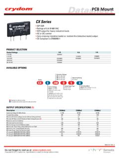
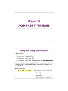
5 Ambient Storage Temperature Range -40 to 125 C. Weight (typical) oz ( g). Housing Material UL94 V-0. Baseplate Material Aluminum Input Terminal Screw Torque Range (in-lb/Nm) 13-15 Load Terminal Screw Torque Range (in-lb/Nm) 18-20 / SSR Mounting Screw Torque Range (in-lb/Nm) 18-20 / Input/Load Terminal Screw Torque Range (in-lb/Nm) (2) w/ K option 8-10 / Input/Output Terminal Screw Thread Size #6-32 UNC / #8-32 UNC. Humidity per IEC60068-2-78 93% non-condensing LED Input Status indicatior w/ G option (green). MTBF (Mean Time Between Failures) at 40 C ambient temperature (11) 11,641,553 hours (1,328 years). MTBF (Mean Time Between Failures) at 60 C ambient temperature (11) 7,210,376 hours (823 years). WIRING DIAGRAM. AC Input Current vs Input Voltage Recommended Wire Sizes V.
6 Terminals Wire Size Wire Pull-Out 25. Load (12) (Solid / Stranded) Strength (lb)[N]. 20. 24 AWG ( mm2) / [minimum]. Input Current (mA). 10 [ ]. 1 ( ) 2 ( ) Input 2 x 12 AWG ( mm2) / [maximum] 90 [400] 15. 20 AWG ( mm2) / [minimum] 30 [133] 10. 1 OUTPUT 2 Output 2 x 10 AWG ( mm2) / 110 [490] 5. 2 x 8 AWG ( mm2) / [maximum]. S O L I D S TAT E R E L AY. 90 [400] 0. 0 5 10 15 20 25 30. 4 INPUT 3. DC Input Voltage 4 ( / ) 3 (+ / ). EQUIVALENT CIRCUIT BLOCK DIAGRAMS. Diagram: HAxxxx Diagram: HDxxxx AC 4 1 AC -DC 4 1 AC. Current Limiter AC/DC. (13). Trigger (14) Trigger (14). Converter Circuit Circuit (13) (15) (15). AC 3 2 AC +DC 3 2 AC. Current Limiter Do not forget to visit us at: Copyright 2016 Crydom Inc. Specifications subject to change without notice.
7 Datasheet Panel Mount MECHANICAL SPECIFICATIONS (). Tolerances: in / mm All dimensions are in: inches [millimeters]. Screw Termination Hex Standoff Termination ( K Option) (2). [ ] Mounting [ ] Mounting [ ] Hole/Slot [ ]. Hole/Slot [ ]. [ ] DIA. [ ] [ ]. DIA. 2 1 OUTPUT 2. 1 OUTPUT. S O L I D S TAT E R E L AY S O L I D S TAT E R E L AY. [ ] [ ] [ ]. [ ] [ ] [ ]. 4 4 INPUT 3. INPUT 3. [ ] [ ]. [ ] (4 places). [ ] [ ] [ ]. (2 places). Quick Connect Termination ( F Option) - Up to 25 Amp (1) Quick Connect Termination ( F Option) - Up to 50 Amp (1). Faston Terminal(16). [ ] Faston Terminal(16) [ ] x Mounting [ ] Mounting (4 places) [ ]. x Hole/Slot Hole/Slot (2 places) [ ] [ ] [ ] [ ]. DIA. [ ]. DIA. (2 places). 1 OUTPUT 2 1 OUTPUT 2.
8 S O L I D S TAT E R E L AY. S O L I D S TAT E R E L AY. [ ] [ ] [ ] [ ] [ ] [ ]. 4 INPUT 3 4 INPUT 3. [ ] Faston Terminal(16) [ ] Faston Terminal(16). x x (2 places) [ ] (2 places). [ ] [ ] [ ]. [ ]. GENERAL NOTES. (1) Single pair (up to 25A) Double pair* (up to 50A). *Caution: User must connect both pairs. (2) Option K is designed and tested for use with printed circuit boards or ring/fork terminals having a thickness between and inches ( to mm), and loads rated up to 50. Amps. For higher load currents, the K standoff temperature must not exceed 105 C. For additional application assistance please contact Crydom Technical Support. (3) Output will self trigger between 900-1200 Vpk, Min. power factor or higher, not suituable for capacitive loads.
9 (4) Instantaneous turn-on version is not recomended for capacitive loads. Use zero turn-on only. (5) All parameters at 25 C unless otherwise specified. (6) For S option, operating voltage frequency is 47-63Hz. (7) For parts with option S maximum leakage current is 10mA. (8) Heat sinking required, see derating curves. (9) Increase minimum voltage by 1V for operations from -20 to -40 C. (10) Turn-on time for instantaneous turn-on versions is msec (DC Control Models). (11) All parameters at 50% power rating and 100% duty cycle (contact Crydom tech support for detailed report). (12) Load can be wired to either SSR output terminal 1 or 2. (13) Elective Input Status LED, G option (14) Elective Overvoltage Protection, P option.
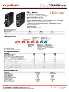
10 (15) Elective Internal Snubber, S option. (16) Mechanical dimensions vary from G3 models. For additional information or specific questions, contact Crydom Technical Support. Do not forget to visit us at: Copyright 2016 Crydom Inc. Specifications subject to change without notice. Datasheet Panel Mount SURGE CURRENT INFORMATION. 12 A 25 A. 120 250. 100 200. Surge Current (Amp). Surge Current (Amp). 80. 150. 60. 100. 40. 20 50. 0 0. 1 10 1 10. Surge Duration (Secs) Surge Duration (Secs). 50 A 75 A. 600 900. 800. 500. 700. Surge Current (Amp). Surge Current (Amp). 400 600. 500. 300. 400. 200 300. 200. 100. 100. 0 0. 1 10 1 10. Surge Duration (Secs) Surge Duration (Secs). 90 A 110 A. 1200 1500. 1050. 1200. Surge Current (Amp).