Transcription of Dell OptiPlex 960 Service Manual
1 dell OptiPlex 960 Service Manual mini Tower Computer Desktop Computer Small Form Factor Computer Back to Contents Page Battery dell OptiPlex 960 mini Tower/Desktop/Small Form Factor Service Manual Replacing the Battery Replacing the Battery A coin-cell battery maintains computer configuration, date, and time information. The battery can last several years. The battery may need replacing if an incorrect time or date is displayed during the boot routine along with a message such as: Time-of-day not set - please run SETUP program or Invalid configuration information - please run SETUP program or Strike the F1 key to continue, F2 to run the setup utility To determine whether you need to replace the battery, reenter the time and date in system setup and exit the program to save the information. Turn off your computer and disconnect it from the electrical outlet for a few hours; then reconnect the computer, turn it on, and enter system setup (see the dell Technology Guide).
2 If the date and time are not correct in system setup, replace the battery. You can operate your computer without a battery; however, without a battery, the configuration information is erased if the computer is turned off or unplugged from the electrical outlet. In this case, you must enter system setup (see the dell Technology Guide) and reset the configuration options. To remove the battery: you have not already done so, make a copy of your configuration information, found in system setup. the procedure Before Working on Your Computer. the computer cover. the battery socket. the system battery. a. Support the battery connector by pressing down firmly on the positive side of the connector. b. While supporting the battery connector, press the battery tab away from the positive side of the connector and pry the battery it up out of the securing tabs at the negative side of the connector. CAUTION: Before you begin any of the procedures in this section, read the safety information that shipped with your computer.
3 For additional safety best practices information, see the Regulatory Compliance Homepage at NOTICE: To prevent static damage to components inside your computer, discharge static electricity from your body before you touch any of your computer's electronic components. You can do so by touching an unpainted metal surface on the computer chassis. CAUTION: A new battery can explode if it is incorrectly installed. Replace the battery only with the same or equivalent type recommended by the manufacturer. Discard used batteries according to the manufacturer's instructions. NOTICE: If you pry the battery out of its socket with a blunt object, be careful not to touch the system board with the object. Ensure that the object is inserted between the battery and the socket before you attempt to pry out the battery. Otherwise, you may damage the system board by prying off the socket or by breaking circuit traces on the system board. NOTICE: To avoid damage to the battery connector, you must firmly support the connector while removing the battery.
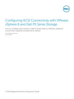
4 The new system battery. a. Support the battery connector by pressing down firmly on the positive side of the connector. b. Hold the battery with the "+" facing up, and slide it under the securing tabs at the positive side of the connector. c. Press the battery straight down into the connector until it snaps into place. the procedure After Working on Your Computer. system setup (see the dell Technology Guide) and restore the settings you recorded in step 1. dispose of the old battery as described in the safety information that shipped with your computer. Back to Contents Page 1 system battery 2 positive side of battery connector 3 battery socket tab 4 battery socket Back to Contents Page Contacting dell dell OptiPlex 960 mini Tower/Desktop/Small Form Factor Service Manual To contact dell for sales, technical support, or customer Service issues: your country or region in the Choose a Country/Region drop-down menu at the bottom of the page.
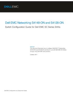
5 Contact Us on the left side of the page. the appropriate Service or support link based on your need. the method of contacting dell that is convenient for you. Back to Contents Page Back to Contents Page Desktop Computer dell OptiPlex 960 mini Tower/Desktop/Small Form Factor Service Manual Inside View of Your Computer Inside View of Your Computer Back to Contents Page 1 drive bays (media card reader, floppy drive, optical drive, hard drive(s)) 2 power supply 3 chassis-intrusion switch 4 system board 5 card slots 6 heatsink assembly 7 front I/O assembly dell OptiPlex 960 Service Manual Notes, Notices, and Cautions If you purchased a dell n Series computer, any references in this document to Microsoft Windows operating systems are not applicable. Information in this document is subject to change without notice. 2008 dell Inc. All rights reserved. Reproduction of this material in any manner whatsoever without the written permission of dell Inc.
6 Is strictly forbidden. Trademarks used in this text: dell , the dell logo, OptiPlex , dell OpenManage and the YOURS IS HERE logo are trademarks of dell Inc.; Intel, Pentium, and Celeron are registered trademarks of Intel Corporation in the and other countries; Microsoft, Windows, Windows Server, MS-DOS and Windows Vista are either trademarks or registered trademarks of Microsoft Corporation in the United States and/or other countries. Other trademarks and trade names may be used in this document to refer to either the entities claiming the marks and names or their products. dell Inc. disclaims any proprietary interest in trademarks and trade names other than its own. Model DCNE December 2008 Rev. A01 Back to Contents Page Desktop Computer Working on Your Computer Inside View of Your Computer System Board Components Cover Chassis Intrusion Switch Cards Drives Processor I/O Panel Power Supply Speakers Battery System Board Memory Troubleshooting Tips Contacting dell NOTE: A NOTE indicates important information that helps you make better use of your computer.
7 NOTICE: A NOTICE indicates either potential damage to hardware or loss of data and tells you how to avoid the problem. CAUTION: A CAUTION indicates a potential for property damage, personal injury, or death. Back to Contents Page dell OptiPlex 960 mini Tower/Desktop/Small Form Factor Service Manual Cards Cards Your dell computer provides the following connectors for PCI and PCI Express (PCIe) cards: l One low-profile PCIe x16 card slot l Two connectors for low-profile PCI cards l One low-profile PCIe x1 card slot l One connector for an internal wireless card PCI and PCIe Cards Installing a PCI Card If you are replacing a PCI card, remove the current driver for the card from the operating system. See the documentation that came with the card for information. the procedure Before Working on Your Computer. press the release tab on the card-retention latch all the way up. CAUTION: Before you begin any of the procedures in this section, read the safety information that shipped with your computer.
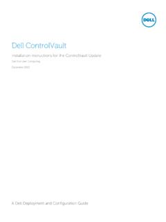
8 For additional safety best practices information, see the Regulatory Compliance Homepage at NOTICE: To prevent static damage to components inside your computer, discharge static electricity from your body before you touch any of your computer's electronic components. You can do so by touching an unpainted metal surface on the computer chassis. NOTE: Installing filler brackets over empty card-slot openings is necessary to maintain FCC compliance of the computer. The brackets help to keep foreign objects out of your computer and help direct airflow for PCIe x1 card 2 PCIe x16 card 3 PCIe x16 riser interface 4 PCIe x1 card 5 release lever, securing tab you are installing a card in an empty card connector on the system board, remove the filler bracket to create a card-slot opening at the back of the computer. Then continue with step 5. you are installing a card to replace one already installed in the computer, remove the installed card (see Removing a PCI Card).
9 The card for installation. 1 card 2 release lever, securing tab 3 system board connector 4 card insert 5 card-retention latch NOTE: See the documentation that came with the card for information on configuring the card, making internal connections, or customizing it for your release tab on card retention latch 2 card 3 card-edge connector 4 card connector CAUTION: Some network adapters automatically start the computer when they are connected to a network. To guard against electrical shock, be sure to unplug your computer from its electrical outlet before installing any cards. the card in the connector and press down firmly. Using the following illustration as a guide, ensure that the card is fully seated in the slot. rotate the release tab downward to move the card-retention latch into place to secure the cards. 1 PCIe x16 card 2 release lever 3 securing slot (not all cards) 4 securing tab 5 PCIe x16 card connector 1 card fully seated 2 card not fully seated 3 bracket within slot 4 bracket caught outside of slot NOTE: If you are installing a PCIe x16 card, ensure that the securing tab on the connector's release lever fits into the slot on the front end of the release tab 2 card-retention latch 3 card 4 card-edge connector 5 card connector any cables that should be attached to the card.
10 The procedure After Working on Your Computer. you installed a sound card: a. Enter system setup, select Audio Controller, and change the setting to Off (see the dell Technology Guide). b. Connect external audio devices to the sound card's connectors. Do not connect external audio devices to the microphone, speaker/headphone, or line-in connectors on the back or front panel. you installed a network adapter card and want to turn off the integrated network adapter: a. Enter system setup, select Network Controller, and change the setting to Off (see the dell Technology Guide). b. Connect the network cable to the connector on the network adapter card. Do not connect the network cable to the integrated network connector on the back panel of the computer. any drivers required for the card as described in the card documentation. Removing a PCI Card the procedure Before Working on Your Computer. rotate upward the release tab on the card-retention latch.