Transcription of Deluge System Technical Manual for Operation, …
1 Deluge SystemTechnical Manual for Operation, maintenance , and TroubleshootingJune, 2009 Form No. F_010708 Page IITECHNICAL DATAThe Viking Corporation, 210 N Industrial Park Drive, Hastings MI 49058 Telephone: 269-945-9501 Technical Services 877-384-5464 Fax: 269-818-1680 Email: 30, 2009 Deluge SPrINkLEr SySTEMT able of ContentsPage I. System DESCrIPTION4 II. System TyPES AND APPLICATIONS4 III. System rEquIrEMENTS4 IV. System OPErATION7A. Deluge System Controlled by Hydraulic release14B. Deluge System Controlled by Pneumatic release14C. Deluge System Controlled by Electric release17 V. Deluge VALVE20A. Description 20B. Accessories21C.
2 Operation22 VI. THErMOSTATIC rELEASES26A. Description 26B. Operation27C. Maintenance27D. Inspection27E. Operational Test27F. Disassembly28g. Adjustment30 VII. FIxED TEMPErATurE rELEASE31A. Description 31B. Operation31C. Maintenance31 VIII. PNEuMATIC ACTuATOr32A. Description 32B. Operation32C. Maintenance32D. Inspection33E. Disassembly33F. reassembly34 Ix. PrESSurE OPErATED rELIEF VALVE (POrV)34A. Description 34B. Operation34C. Inspections, Tests, and Maintenance34 x. SOLENOID VALVE36A. Description 36B. Operation36C. Inspections, Tests, and Maintenance36 xI. EMErgENCy rELEASE37A. Description 37B. Operation37C. Maintenance37D. Inspection38E. Testing38 Technical DATAThe Viking Corporation, 210 N Industrial Park Drive, Hastings MI 49058 Telephone: 269-945-9501 Technical Services 877-384-5464 Fax: 269-818-1680 Email: SPrINkLEr SySTEMPage IIIJune 30, 2009 Table of Contents ContinuedPage xII.
3 RELEASE CONTrOL PANEL38A. Description 38B. Operation38C. Inspections, Tests and Maintenance38 xIII. rELEASE LINE AIr SuPPLy ASSEMBLy38A. Description 38B. Operation39C. Maintenance39 xIV. AIr SuPPLIES FOr rELEASE SySTEMS40A. Description 40B. Model C-1 Thermostatic release Systems with a Bottled gas Supply41 xV. DEHyDrATOr41A. Description 41B. Operation41C. Maintenance41D. Disassembly42E. reassembly42 xVI. wATEr-SPrAy FIxED SySTEMS42A. System Applications42B. general requirements43C. System Components44D. Hydraulic Calculations and required Density48E. Exposure Protection of Transformers48F. Exposure Protection of Flammable Liquid Storage50g. Exposure Protection of Structural Steel51H.
4 Exposure Protection of Metal Pipe, Tubing, and Conduit52I. Exposure Protection of Cable Trays and Cable runs52J. Fire Extinguishment Protection of Cable Trays and Cable runs53k. Fire Extinguishment Protection of Belt Conveyors53L. Control of Burning54M. Prevention of Fire54N. Automatic Detection Systems and Equipment55O. water Spray System Maintenance57 xVII. PLACINg THE Deluge System IN SErVICE57 xVIII. Deluge System INSPECTIONS, TESTS, AND MAINTENANCE58A. quarterly water Flow Alarm Test58B. quarterly Main Drain Test59C. Annual Trip Test59D. Maintenance60 xIx. rEMOVINg THE System FrOM SErVICE62 xx. TrOuBLESHOOTINg VIkINg Deluge SySTEMS63A. POrV63B. Pneumatic Actuator64 Page Technical DATAThe Viking Corporation, 210 N Industrial Park Drive, Hastings MI 49058 Telephone: 269-945-9501 Technical Services 877-384-5464 Fax: 269-818-1680 Email: 30, 2009 Deluge SPrINkLEr SySTEMI.
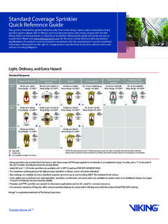
5 System DESCrIPTIONA Deluge System is a fixed fire protection System in which the pipe System is empty until the Deluge valve operates to distribute pressurized water from open nozzles or sprinklers. Deluge systems are more com-plex than wet pipe and dry systems because they contain more components and equipment. The Deluge valve is activated by operation of a fire detection System installed in the same area as the sprinklers (Figure 1). Various types of detection systems may be used, including smoke, heat, ultraviolet (UV), or infrared (IR) detection. The Viking Deluge System can be activated by a hydraulic, pneumatic, electric, or Manual release System or any combination of these release systems.
6 But, in all cases, the Deluge valve itself is activated hydraulically. When the detection device is activated, the Deluge valve is tripped and water flows into the piping System , discharging through all spray nozzles or sprinklers simultaneously (Figure 2). This Technical Manual will cover Viking Deluge System design calculation, trim parts and their functions, as well as describe the proper operation, maintenance , and repair of valves and System TyPES AND APPLICATIONSD eluge systems are used where conditions of occupancy or special hazards require quick application of large quantities of water. These systems are used to create a buffer zone in high-hazard areas or in areas where fire may spread rapidly, and they can also be used to cool surfaces to prevent deformation or struc-tural collapse or to protect tanks, process lines, or transformers against explosion.
7 Other examples include storage or process areas containing substances having a low flash point; tanks containing combustible solutions, equipment pits or product handling systems. When designing a Deluge System , efforts should be made to acquire specific information regarding the hazard to be protected. Foam-water Deluge systems are those using foam-water sprinklers or spray nozzles and an air-foam con-centrate which is introduced into the water at controlled rate on the System side of the Deluge valve. Foam water systems are used to control and/or extinguish fires which require a smothering and cooling agent. Examples are: extraction plants, aircraft hangars and areas where flammable-liquid spill fires may Deluge Systems: TRIMPAC is a factory assembled trim package with a specific release device and release module (pneumatic or electric) in a metal enclosure.
8 The standard trim normally required on a Deluge valve has been moved to a single cabinet. TRIMPAC provides access doors for the emergency release and alarm test valve for Manual operation of these trim valves. TRIMPAC is equipped with prim-ing water pressure and water supply gauge view-ports for easy monitoring of water pressures. TRIMPAC eliminates the installation of alarm trim piping and release trim piping at the Deluge valve. The enclosure protects trim valves from inadvertent operation. Piping (or the included stainless steel hose package) from the valve body to the enclosure assembly allows the assembly to be installed remote of the sprinkler sys-tem riser.
9 TRIMPAC can be utilized for pneumatic or electric release Deluge systems regardless of valve size. A valve drain package for the Deluge valve is required and is ordered based on the Deluge valve size. Refer to sections in this Manual specifically for TRIMPAC .NOTE: SPRINklER SySTEMS ARE ENgINEERED TO MEET ThE STANDARDS OF NFPA 13, FM glOBAl, lOSS PREVENTION COUNCIl (FOC), ASSEMBlEE PlENIERE, VERBAND DER SAChVERSIChERER (VDS) OR OThER SIMIlAR ORgANIzATIONS, AND WIll AlSO NEED TO COMPly WITh ThE PRO VISIONS OF gOVERNMENTAl CODES, ORDINANCES, AND STANDARDS WhERE APPlICABlE. ThE System MUST BE DESIgNED By qUAlIFIED DESIgN PROFESSIONAlS IN CONJUNCTION WITh INSURINg BODIES.
10 ThE USER IS RESPONSIBlE FOR ThE DESIgN AND CONFIgURATION OF ThE System , ITS APPROPRIATENESS FOR ThE USE INTENDED AND ITS COMPlIANCE WITh All STANDARDS, CODES AND ORDINANCES. VIkINg CORPORATION DOES NOT DESIgN SySTEMS FOR SPECIFIC INSTAllATIONS AND MAkES NO REPRESENTATION OR WARRANTy CONCERNINg WhEThER ANy SPECIFIC System INSTAllATION WIll BE SUFFICIENT FOR ThE INTENDED USE OR WIll COMPly WITh ANy STANDARD, CODE, OR ORDINANCE. ANy System DEPICTED IN ThIS Manual IS ShOWN FOR IllUSTRATIVE PURPOSES DATAThe Viking Corporation, 210 N Industrial Park Drive, Hastings MI 49058 Telephone: 269-945-9501 Technical Services 877-384-5464 Fax: 269-818-1680 Email: SPrINkLEr SySTEMPage June 30, 2009 Figure 1 Page Technical DATAThe Viking Corporation, 210 N Industrial Park Drive, Hastings MI 49058 Telephone: 269-945-9501 Technical Services 877-384-5464 Fax: 269-818-1680 Email: 30, 2009 Deluge SPrINkLEr SySTEMF igure 2 Technical DATAThe Viking Corporation, 210 N Industrial Park Drive, Hastings MI 49058 Telephone: 269-945-9501 Technical Services 877-384-5464 Fax.