Transcription of DESCRIPTION - UPGNET
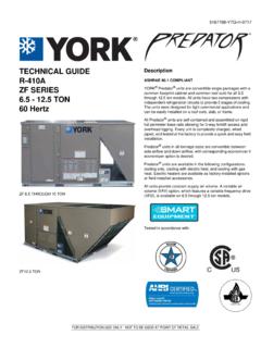
1 TECHNICAL GUIDELX SERIESSPLIT-SYSTEM AIR CONDITIONERS13 SEER R-410A 1 THRU 5 NOMINAL TONSMODELS: YCJD18 THRU 60 Due to continuous product improvement, specifications are subject to change without us on the web at and rating information can be found SUMMARY*Standard 5-Years limited parts 10-Years limited compressor 10-Years limited parts warranty when product isregistered online within 90 days of purchase for replacementor closing for new home construction.*Does not apply to R-22 models, 3-Phase models, or internet Limited Warranty certificate in User's Information Manual for details. 840569-YTG-C-1112 FOR DISTRIBUTION USE ONLY - NOT TO BE USED AT POINT OF RETAIL SALEDESCRIPTIONThe 13 SEER Series unit is the outdoor part of a versatile cli-mate system.
2 It is designed with a matching indoor coil compo-nent from Johnson Controls Unitary Products. Available fortypical applications this climate system is supported with acces-sories and documents to serve specific Small Footprint - Extremely lightweight with a compact foot-print, it is a perfect fit for any application. Quality Condenser Coils - The coil is constructed of alumi-num microchannel tubing and enhanced aluminum fins forreduced size and increased efficiency. Coil Protection - Coils are protected from damage by a slot-ted, stamped steel coil guard and secondary polymer mesh. Optional Factory E-Coat - Available ElectroFin coated coilon select models. Protected Compressor - Compressors are protected inter-nally by a high pressure relief valve and a temperature sen-sor, and externally by the system high pressure switch.
3 Afactory installed liquid line filter-drier further protects thecompressor against moisture and debris. Environmentally Friendly Refrigerant - The next genera-tion refrigerant R-410A delivers environmentally friendly per-formance with zero ozone depletion. Durable Finish - The cabinet is made of G90-equivalent pre-painted steel, with special primer formulas and matte cham-pagne texture to insure less fading when exposed to sun-light. The coated steel wire fan guard and pre-treated,galvanized steel chassis components resist corrosion andrust creep. Lower Installed Cost - Installation time and costs arereduced by easy power and control wiring connections. Theunit is factory charged for a 15-foot lineset.
4 The small basedimension means less space is required on the ground orroof. Top Discharge - Warm air from the top mounted fan is blownup, away fro0m the structure and any landscaping. Thisallows compact location on multi-unit applications. Low Operating Sound Levels - The upward air flow carriesthe normal operating noise away from the living area. Therigid top panel effectively isolates any motor sound. Isolatormounted compressor and the condenser coil muffle the nor-mal fan motor and compressor operating sounds. Low Maintenance - Long life, permanently lubricated motor-bearings need no annual servicing. Easy Service Access - Fully exposed refrigerant connec-tions and a single panel covering the electrical controls makefor easy servicing of the unit.
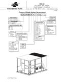
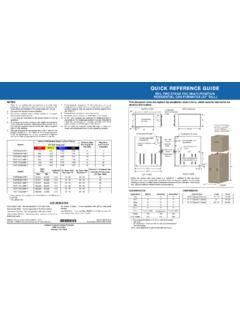
5 Secured Service Valves - Secured, re-usable servicevalves are provided on both the liquid and vapor sweat con-nections for ease of evacuating and charging. Agency Listed - Safety certified by CSA to UL 1995 / Performance certified to ANSI/AHRI Standard 210/240in accordance with the Unitary Small Equipment Controls Unitary ProductsAll dimensions are in inches and are subject to change without height is from bottom of basepan to top of fan length and width include screw and Electrical DataMODELYCJD18S41S1(H)(E)YCJD24S41S1(H) (E)YCJD30S41S1(H)(E)YCJD36S41S1(H)(E)YCJ D42S41S2(H)(E)YCJD48S41S1(H)(E)YCJD60S41 S2(E)Unit Supply Voltage208-230V, 1 60 HzNormal Voltage Range 1187 to 252 Minimum Circuit Overcurrent Device Amps 215202530353560 Min.
6 Overcurrent Device Amps 315151520252535 Compressor Type RotaryRecipRecipRecipRecipRecipScrollCom pressor AmpsRated Rotor404354748884134 Crankcase HeaterNoNoNoNoNoNoNoFactory External Discharge MufflerNoNoNoNoNoYe sNoFactory External Check ValveNoNoNoNoNoNoNoHS Kit Required with TXV 4Ye sYe sYe sYe sYe sYe sNoFan Motor AmpsRated Diameter MotorRated HP1/121/81/41/41/41/41/4 Nominal RPM110010751100850850850850 Nominal CFM1400195020503200305029503400 CoilFace Area Sq. Deep1111111 Fins / Inch23232323232323 Liquid Line Set OD (Field Installed)3/83/83/83/83/83/83/8 Vapor Line Set OD (Field Installed)5/83/43/43/47/87/87/8 Unit Charge (Lbs. - Oz.) 53 - 33 - 133 - 144 - 94 - 104 - 95 - 8 Charge Per Foot, Weight with "H" on the end of the model number are shipped with a Hard Start Kit installed at the with E on the end of the model number have an ElectroFin coating on the outdoor Rated in accordance with AHRI Standard 110-2012, utilization range A.
7 2. Dual element fuses or HACR circuit breaker. Maximum allowable overcurrent Dual element fuses or HACR circuit breaker. Minimum recommended overcurrent See Hard Start Kit Accessory Installation Manual for Hard Start Kit part number for each model. 5. The Unit Charge is correct for the outdoor unit, smallest matched indoor unit, and 15 feet of refrigerant tubing. For tubing lengths other than 15 feet, add or subtract the amount of refrigerant, using the difference in length multiplied by the per foot (Inches)Refrigerant ConnectionService Valve SizeABCL iquidVapor1828-1/424243/83/42428-1/42424 3028-1/424243628-1/429-1/229-1/24230-1/4 29-1/229-1/27/84830-1/429-1/229-1/26032- 1/43434840569-YTG-C-1112 Johnson Controls Unitary Products3 PROCEDURES:1.
8 Unit factory charge listed on the unit nameplate includes refrigerant for the outdoor unit, the smallest matched indoor unit, and 15 feet of interconnecting line Verify the TXV or orifice and additional charge required for specific matched indoor unit in the system using the above Add additional charge for the amount of interconnecting line tubing greater than 15 feet at the rate specified in Physical and Electrical Data For indoor matches requiring additional charge, the refrigerant needs to be weighed in for specific matched indoor unit and lineset Permanently mark the unit nameplate with the total system charge. Total System Charge = Base Charge (as shipped) + charge adder for matched indoor unit + charge adder for line Charge for Various Matched SystemsOutdoor Unit YCJD18S41S1(H)(E)YCJD24S41S1(H)(E)YCJD30 S41S1(H)(E)YCJD36S41S1(H)(E)YCJD42S41S2( H)(E)YCJD48S41S1(H)(E)YCJD60S41S2(E)
9 Required Orifice or TXV 1, Unit 3,4,5 Additional Charge, AHE24B 4 AHE30B 40 AHE36C 420 AHE42D 810 AHE48D 90 AHE60D 14 4 AHR18B0 AHR24B 4 AHR30B 0 AHR36B 20 AHR42C 810 AHR48D 90 AHR60D 15 4 AHV18B0 AHV24B148 AHV30B1480 AHV36C221460 AHV42D 181010 AHV48D 1093 AHV60D 1384AV*24 TXV + 0 AV*36 420 AV*48 TXV + 100 AV*60 TXV + 1000FC/MC/PC180 FC/MC/PC32 40 FC/MC/PC35 40 FC/MC/PC36 0 FC/MC/PC37 420 FC/MC/PC43 4200 FC/MC/PC48 8104 FC/MC/PC60 900FC/MC62 14 4FC64 23 11UC180 UC36 0 UC48 844 UC60 900 Some of the combinations shown in the above System Charge table require Advanced Main Air Circulating Fan indoor product.
10 For approved coil only matches, please see the COOLING CAPACITY - Upflow, Downflow & Horizontal Furnaces and Coils :1. For applications requiring a TXV use S1-1 TVM** series Approved orifice(s) shipped with outdoor Systems matched with furnaces or air handlers not equipped with blower-off delays may require blower Time Delay Kit PC coils cannot be used in downflow or horizontal applications. FC coils cannot be used in horizontal Refer to Cooling Performance Data tables for actual system performance for specified system 12-48 require Hard Start Kits for TXV matches. Models with H on the end of the model number have factory installed Hard Start models without an H refer to the Hard Start Kit Accessory Installation Manual for the Hard Start Kit part number for each Controls Unitary ProductsCOOLING CAPACITY - With Air Handler CoilsUNITMODELAIR HANDLERCOILMODEL1 COOLINGMODELWIDTHRATEDCFMNET SEER AC WITH AIR HANDLERSYCJD18S41S1(H)(E) * (H)(E) * (H)(E) * (H)(E) * Notes See Page Controls Unitary Products5 = Not Modular Air Handlers use Coil Only (H)(E) * * (H)(E) * * (E) * in accordance with DOE test procedures (Federal Register 12-27-79 and 3-18-88)