Transcription of DESIGN AND ANALYSIS OF TELESCOPIC HALFSHAFT FOR AN …
1 ISSN: 2277-9655 [Patil et al., 5(10): October, 2016] Impact Factor: IC Value: CODEN: IJESS7 http: // International Journal of Engineering Sciences & Research Technology [454] IJESRT INTERNATIONAL JOURNAL OF ENGINEERING SCIENCES & RESEARCH TECHNOLOGY DESIGN AND ANALYSIS OF TELESCOPIC HALFSHAFT FOR AN ALL-TERRAIN VEHICLE (ATV) Chirag Patil *, Sandeep Imale, Kiran Hiware, Sumeet Tiwalkar * Department of Mechanical Engineering, Jawaharlal Nehru Engineering Collage, Aurangabad, India DOI: ABSTRACT Torque transmission from differential to the wheels is a prime factor of driveshaft. A half-shaft transmits the drive from differential to the wheel hub. TELESCOPIC half-shaft is one of the advancement coming up in automobile industries.
2 TELESCOPIC axles that feature a unique slip joint DESIGN in the main shaft that allows the axles to extend and compress slightly during suspension travel to help relieve added stress to the axle joints and to help prevent the axle from pulling from the differential. In this study, a TELESCOPIC half-shaft was designed and analyzed for its use in an all-terrain vehicle (ATV). The entire DESIGN of half-shaft was done theoretically by using maximum principal shear stress theory and maximum shear stress theory. Models were prepared using 3D technique in SOLIDWORKS 2016 and ANALYSIS was done using ANSYS Workbench TELESCOPIC half-shafts used in an all-terrain vehicle was seen to be effective. KEYWORDS: Drive-train, Driveshaft, TELESCOPIC , Half-shaft ANALYSIS , SOLIDWORKS, ANSYS INTRODUCTION A half-shaft transmits the drive from the differential to the wheels.
3 Half-shafts are needed to transfer the torque from the transmission to the drive wheels at a constant speed while accommodating the up and down motion of the suspension. A driveshaft consists of the half-shaft and two constant velocity (CV) joints, used on both ends of half-shaft. It is used to provide a certain degree of angular displacement. Suspension geometry designed for an all-terrain vehicle (ATV) requires a shaft to stroke more lateral movement than conventional actual shafts. Because of high travel rear suspension geometry, results in axles getting out of the gearbox. In order to increase performance of suspensions, to maintain high ground clearance, it is very important to increase the lateral movement of the half-shaft. A TELESCOPIC half-shaft designed in this study comes with unique slip joint in the main shaft that allows the axle to extend and compress slightly during suspension travel to help relieve added stress to the axle joints and to help prevent the axle from pulling from differential.
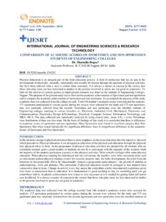
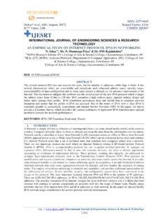
4 This results in more lateral movement than conventional shafts and increase in travel performed by the suspension geometry. This TELESCOPIC half shaft is designed for an all-terrain vehicle (ATV) made for competition called BAJA. BAJA event held by Society of Automotive Engineers (SAE) is a competition among students, where they are challenged to DESIGN , build and test on ATV following rules and specifications designed by the society of automotive engineers. Assembled view and exploded view of TELESCOPIC driveshaft ISSN: 2277-9655 [Patil et al., 5(10): October, 2016] Impact Factor: IC Value: CODEN: IJESS7 http: // International Journal of Engineering Sciences & Research Technology [455] MATERIALS AND METHODS A tough, hard material must be used to withstand the various stresses, resist splines wear and provide good resistance to fatigue.
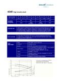
5 Material used for half-shaft: AISI/SAE 4340 Chromoly (quenched and tempered) Table 1. Mechanical properties of AISI/SAE 4340 Parameters Values Density g/cm3 Elongation 14% Tensile yield strength 1110 Mpa Ultimate yield strength 1294 Mpa DESIGN procedure for half-shaft The various important parameters are stated below. Gross vehicle weight = 250 kgs Weight distribution = front-100kgs, Rear-150kgs Engine power = 10HP Maximum engine torque = at 2800 RPM Engine Maximum RPM = 3800 RPM Tyre size = 23 7 12 inch Length of axle = mm Various stresses acting on half-shaft are- 1. Shear stress due to weight of the vehicle. 2. Torsional stress due to driving torque. 3. Bending stress due to weight of the vehicle (when shaft is subjected to pure bending). 4. Tensile and compressive stress due to cornering forces.
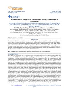
6 The diameter of the shaft is calculated using Maximum principle shear stress theory and Maximum shear stress theory . t > Syt/2 and max < we took factor of safety as Bending moment (Mb) = W* *L= 250* * Mb = N-m Bending stress ( b) = 32Mb/ d3 = /d3 N/m2 Now, Torsional shear stress ( ) = 16Mt/ d3 = N/m2 By using maximum principle shear stress theory; t = ( b/2) + (( b/2)2 + 2)1/2 t= N/m2 By using maximum shear stress theory; max= (( b/2)2 + 2)1/2 max= N/m2 Now, t > Syt/2 1110/2 d = mm ISSN: 2277-9655 [Patil et al., 5(10): October, 2016] Impact Factor: IC Value: CODEN: IJESS7 http: // International Journal of Engineering Sciences & Research Technology [456] max < = (1110)/2 d = mm Half Shaft diameter (d) = mm Major diameter of slip joint splines = mm Minor diameter of slip joint splines = mm FINITE ELEMENT ANALYSIS The model of shaft was prepared using 3D technique in SOLIDWORKS.
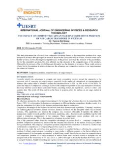
7 Then model is then transferred in .iges format and exported into the ANSYS for ANALYSIS of half-shaft. Finite element ANALYSIS is applied in engineering is a computational tool for performing engineering ANALYSIS it includes the use of mesh generation techniques for dividing a complex problem into small elements. Discretization may be simply described as process by which the given body is subdivided into equivalent systems of finite elements. The meshing is adequately done to obtain the accurate results while computation. Model is meshed with element type tetrahedron shape with element size of 1mm where number of elements are 899637 and number of nodes are 1503560. Figure: Meshed model with 1 mm element size ISSN: 2277-9655 [Patil et al.]
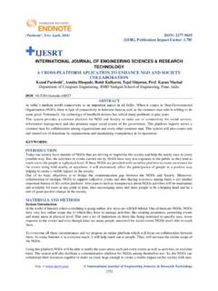
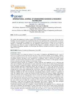
8 , 5(10): October, 2016] Impact Factor: IC Value: CODEN: IJESS7 http: // International Journal of Engineering Sciences & Research Technology [457] Loading and Boundary conditions Preliminary stage of any static ANALYSIS is to decide the loading and boundary conditions. The torque is transmitted to and from the half-shaft via splines on both ends of the component, so they are subjected to torsion and shear stress. The gearbox reduction was :1 and CVT min. reduction was 3:1, so overall reduction with efficiency 85% was :1 which was further multiplied by engine torque at 1800 rpm with efficiency 85% of transmission gave maximum torque output of N-m at wheels. This torque was then used to verify the torsional strength of half-shaft.
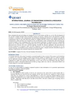
9 The outer end of shaft was fixed, while the N-m of torque was applied to inner end. Figure: Results of max shear stress, max deformation and max principle stress shown by ANSYS ISSN: 2277-9655 [Patil et al., 5(10): October, 2016] Impact Factor: IC Value: CODEN: IJESS7 http: // International Journal of Engineering Sciences & Research Technology [458] The results of ANSYS shows that the maximum stress operated in the component is at end of slip joint spline of male part as shown in figure3. The max stress is of and maximum deformation is both this values are within the safety limit. RESULTS AND DISCUSSION Our goal is to DESIGN a TELESCOPIC axle which gives more lateral stroke than conventional shaft, overall this project is a success.
10 Permissible stress can be determined by the material properties and actual stress can be determined by modeling and finite element ANALYSIS . Stresses and deformation obtained are within the permissible range to avoid static and fatigue failure. For an off-road application, where the vehicle requires high ground clearance and high suspension travel, unique feature of this TELESCOPIC axle makes this component a vital device. The driveshaft designed in this study gives lateral movement up to 50mm which is more than enough travel for suspension geometry which results in better shock absorber performance with up and down motion of axles. CONCLUSION In this paper we have done the DESIGN and ANALYSIS of TELESCOPIC half-shaft to increase the lateral stroke of the axle and to improve the performance of suspension geometry.