Transcription of Design of a Dual Patch Triangular Microstrip …
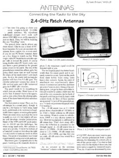
1 Patch AntennaDesign of a dual PatchTriangular Microstrip AntennaDual patches offer wider bandwidth for wireless applicationsin the GHz ISM bandBy S. H. Al-Charchafchi, W .K. Wan Ali, M. R. Ibrahim and S. R. BarnesCranfield College of Aeronautics, Cranfield UniversityThis paper investigates the Design ,measurement and characteristicsof a probe-fed dual Patch equilat-eral Triangular antenna . A lossless foammaterial is sandwiched between the twopatches to provide a mechanically stableand uniform height.
2 It is shown that theseparation height between the twopatches plays a significant role inimproving the impedance bandwidth ofthe antenna . A bandwidth of per-cent is measured around a center fre-quency of GHz. Measurements ongain and polar patterns are also pre-sented. This antenna could find usefulapplications in the industrial, scientificand medical (ISM) frequency the last two decades, a con-siderable number of papers have been publishedon the performance and applications ofmicrostrip Patch antennas [1-4].
3 Various patchconfigurations such as annular-ring, disk, rec-tangular and Triangular have been Patch antennas possess many desirablefeatures, such as low profile, light weight, lowcost, direct integrability with microwave circuit-ry and the ability to conform to the surface of ahost object. Such features make microstrippatch antennas useful for many applications inradar and wireless communication , one of the principal limitations ofsuch antennas is their very narrow bandwidth,which is on the order of a few percent.
4 Manybandwidth enhancement techniques have beensuggested and implemented in recent years, andone such technique is stacking patches eitherhorizontally or vertically [5-7]. In this paper, wepresent an experimental investigation on broad-banding the impedance bandwidth of a vertical-ly stacked equilateral Triangular Patch equilateral Triangular Patch configurationis chosen because it has the advantage of occu-pying less metalized area on the substrate thanother existing lossless foam material is used to control thedistance between the two patches and to providea mechanically stable height separation.
5 Inpractice, it was found that the height separationplays a significant role in achieving the opti-mum impedance bandwidth of the antenna . Thedescribed antenna has an impedance bandwidthof percent with the two ends of the fre-quency band being at GHz and GHzrespectively. Measurements of antenna gain andradiation patterns are also Design procedureFigure 1 shows the configuration of thestacked Triangular Patch antenna that was con-sidered in this paper. The Design procedurestarts with the determination of the sidelengthof the driven Patch using the resonant frequen-60 Applied Microwave & Wirelesssubstrate thicknessh= mmfoam thicknessSsubstrate thicknessh= mmcoax feeddriven patchparasitic patchnFigure 1.
6 Layout of the stacked Triangular Patch Antenna62 Applied Microwave & Wirelesscy formula. Several papers [8-13, 15] on the resonantfrequencies of equilateral Triangular Patch antenna havebeen published. All of these papers agree on the basicequation for the resonant frequency given by(1)where m,nandlare the mode integers due to the elec-tric and magnetic boundary conditions,cis the speed oflight in free space, is the dielectric constant and aisthe sidelength of the equilateral , several methods for correcting the side-length due to the effect of the fringing fields have beendiscussed by various authors.
7 The simplest correctionwas given by Dahele and Lee [8]:(2)where aeffis the effective sidelength, his the substratethickness and ais the actual sidelength of the equilater-al and Lee also reported that, when aeffis used toreplace the value of ain Equation (1), this correctionwould give a 2 percent error on the calculated resonantfrequency. Gang [9] proposed another version of aeffwhich keeps the same expression as that given inEquation (2) but uses the effective dielectric constantgiven by the following formula.
8 (3)where(4)(5)For thin substrates that is, for small h/a theaccuracy of Equation (2) with rreplaced by effis notmuch better than that of Dahele and Lee [8] because effis approximately equal to and Long [10] put forward the idea that thefringing fields for an equilateral Triangular microstrippatch can be considered equal to that of a disk havingthe same metalized area. The equivalent radius of thedisk is given by(6)where aeqis the equivalent radius and Sis the actualarea of the equilateral was accepted that the effective radius of the disktakes into account the fringing effect is given by(7)where the effective radius of the disk and aristhe actual radius of the aeqinto equation (7) gives(8)Garg and Long [10] also suggested that the effectivesidelength calculated from Equation (8) should be usedto replace the value of ain Equation (1)
9 While keeping rconstant. Suzuki and Chiba [11] put forward a formulathat took into account the effect of fringing field for anarbitrary shape Patch . Based on this formula, Singh, Deand Yadava [12] proposed that the effective sidelengthbe given by(9)where aeqand aeff1are calculated using equations (6)and (8) respectively. Another formulation for the effec-tive sidelength was given by Kumprasert and Kiranon[13], which was derived from an expression for thecapacitance of a disk Patch antenna given by Chew andKong [14].
10 The formula for aeffis given byaaaaeffeffeq21=FHGIKJ aahaaheffrreqeq11221 7726=+FHGIKJFHGIKJ+ +FHGIKJFHGIKJ+1221 7726 aSeq= AhHa==6332 and tAHH A HAHHAAH=+ +++bgbgejbglnln2 effrrt=++ 121121bgbgbgaaheffr=+ fcammnnmnlr,,=++2322 nFigure 2. Return loss vs. Antenna64 Applied Microwave & Wireless(10)Also, a paper was published by Guney [15], who pro-posed another expression for the effective sidelength. Inthat paper he used the term eff, given by Equation (3),and a formula for aeffgiven by(11)In the present investigation, the formula given byKumprasert and Kiranon [13] is used because the corre-lation achieved between the theoretical and experimen-tal values of the resonant frequency is the most accu-rate.

