Transcription of DESIGN OF BEAM-COLUMNS-I - Steel ..." INSDAG
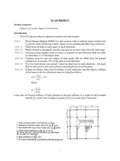
1 DESIGN OF BEAM-COLUMNS-I DESIGN OF beam - columns - I 13 INTRODUCTION columns in practice rarely experience concentric axial compression alone. Since columns are usually parts of a frame, they experience both bending moment and axial force. The frames, in which columns are members, may be classified as braced or unbraced. In braced frames the resistance to lateral loads at floor levels is provided either by bracings [Fig. 1(b)] or shear walls. In case of unbraced frames [Fig. 1(d)] the resistance to lateral loads is obtained from the members of the frames with moment resisting connections between them.
2 Thus the relative translation between the ends of a column in a braced frame is prevented, whereas in unbraced frames the columns are free to sway causing relative translation between their ends. More details on classification of frames as braced and unbraced are given in the chapter on frames. Thus columns in practice experience bending about one or both axis in addition to axial compression, due to one or more of the following reasons. The compressive force may be eccentrically transferred to the column [Fig.]
3 1(a)]. When this eccentric force is transferred to the centre line of the column, an equivalent axial compression and bending moment act on the column. When the beams in braced rigid portal frames are subjected to gravity loads, the rotation of the beams at their junction with the column causes rotation of the column also at the junction due to rigid connection [Fig. 1(b)]. Hence beam transfers bending moments to the column in addition to axial load [Fig. 1(c)]. When a multi-storey multi-bay un-braced frame is subjected to gravity loads and lateral loads due to wind or earthquake, the columns are subjected to sway deflection and bending [Fig 1(d)].
4 In such cases, the columns experience axial compression as well as bending moments [ (e)]. Beams may frame from two orthogonal directions in corner columns in buildings [Fig. 1(f)]. In such cases the columns may be subjected to bending about both principal axes in addition to axial compression [Fig. 1(f)]. columns subjected to combined axial force and bending moment are referred to as beam - columns . A beam -column may be subjected to single curvature bending over its length [Fig.]
5 1(c)]. In this case the nature of the bending stress (compressive or tensile) at a point in the cross section and sign of the bending moment diagram over its entire length of the beam -column remains the same. Consequently, the curvature has the same sign over the entire length of the column. On the other hand, the columns in a sway frame [Fig. 1(d)] Copyright reserved Version II 13-1 DESIGN OF BEAM-COLUMNS-I experience reverse curvature bending as shown in Fig. 1(e), causing variation of the nature (positive or negative) of the bending moment and curvature over the length of the column.
6 (c) (d) (b) x(f) z y Fig. 1 beam - columns in Frames (a) Presence of bending moments in the beam - columns reduces the axial force at which they fail. This topic presented in two parts, deals with the behaviour, and DESIGN of beam -Version II 13-2 DESIGN OF BEAM-COLUMNS-I columns . In Part I initially, the behaviour and strength of short beam -column members under combined compression and bending moment are discussed. In such short beam column the failure is due to the strength of the material being reached (material failure).
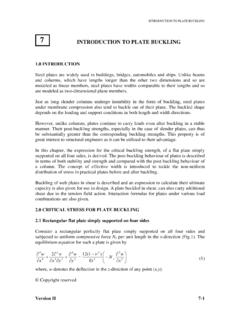
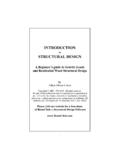
7 Subsequently, the behaviour and strength of practical, long beam - columns , as affected by stability and deformation, are discussed. In long columns the failure may be either due to material strength being reached at the ends of the column or instability of the overall column. In Part II equations for the DESIGN of beam - columns subjected to combination of axial compression and biaxial bending are presented. A DESIGN example of a beam -column also is presented in Part II. SHORT beam - columns A short member (stub column), made of non-slender (plastic, compact or semi-compact) section under axial compression, fails by yielding (due to large deformation) at the squash load, Pd, given by [Fig.]
8 2(a)] Pd = Ag fy (1) where, fy is the yield strength of the material, and Ag is the gross area of the cross section. If the stub column is made of slender cross section, the plate elements of the cross section undergo local buckling before reaching the yield stress. This causes reduction in the effective area of the cross section to a value below the gross area, Ag, and the member fails at a load below Pd, given by Similarly a short member made of plastic or compact section and subjected to only bending moment fails at the plastic moment capacity, Mp, given by [Fig.
9 2(b)] Mp = Zp. fy (2) where, Zp = plastic section modulus of the cross section, in the case of plastic and compact sections. (a) Only axial compression moment fy (b) Only bending(c) Combined compression and bending moment P M fy Section =fy +fy fy fy fy fy fy Fig. 2 Stresses in Short beam - columns A semi-compact section subjected to bending moment only fails by buckling of a plate element of the cross section before the plastification of the entire section as shown in Fig.
10 2 (b) but after the stress at the extreme fibre in compression reaches the yield stress. In a Version II 13-3 DESIGN OF BEAM-COLUMNS-I slender section, the plate elements buckle even before the extreme fibre stress in bending reaches the yield stress. Consequently, the semi-compact and slender sections fail under bending even before reaching the plastic moment, Mp, given by Eqn. 2. The discussions that follow generally assume that the cross section is either plastic or compact. In the case of slender and semi-compact sections the effect of earlier failure before complete section yielding has to be considered.