Transcription of Design of Reinforced Concrete Beams per ACI 318-02
1 PDHonline Course S152 (3 PDH) Design of Reinforced ConcreteBeams per ACI 318-022012 Instructor: Jose-Miguel Albaine, , Online | PDH Center5272 Meadow Estates DriveFairfax, VA 22030-6658 Phone & Fax: Approved Continuing Education PDH Course S152 Page 1 of 21 Design of Reinforced Concrete Beams per ACI 318-02 Course Content A) Flexural Strength of Reinforced Concrete Beams and Slabs 1. Introduction The Design of Reinforced Concrete structural members may be done by two different methods. One, called working stress Design (WSD), is based on the straight-line distribution of compressive stress in the Concrete (Fig.
2 1), covered in Appendix B by ACI 318. This method was the prevalent methodology up until the 1971 edition of the ACI code, and the evaluation is accomplished using service loads. The other is known as the strength Design method or ultimate strength Design (USD), and is the predominant Design method used in the Design of Reinforced Concrete structures. This method will predict with satisfactory accuracy the maximum load that the structural member under consideration will carry. The actual distribution of the compressive stress in a section has the form of a rising parabola (Fig. 2a), and an equivalent rectangular stress block (Whitney block, Fig.
3 2b) can be used without loss of accuracy to calculate the flexural moment strength of a section. This USD method will be covered solely in this course. Other important stresses present in Beams are shear stresses. These stresses are uniquely significant in Concrete Beams because when they combined with longitudinal stresses (due to flexure), they produce inclined stresses (diagonal tension) which in term induce diagonal cracks. The basic mechanism of these sloping cracks is the lack of tensile strength inherent in Concrete . For practical considerations the intensity of the vertical shear is deemed to be a measured of the intensity of the diagonal tension.
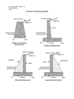
4 The ACI code evaluates the shear strength of Concrete section as being made up of two components: a) the shear strength of the uncracked Concrete section, and b) the strength of the steel shear reinforcement. Shear is covered in ACI Chapter 11. The following Concrete structural elements are designed using the principles addressed in this course once the internal forces are determined: floor slabs, Beams , girders, footings, and retaining walls. PDH Course S152 Page 2 of 21 Figure 1 Figure 2a Figure 2b 2.
5 Design Assumptions The ACI code covers the Design assumptions for flexural strength under Chapter 10, section fc1/3 kdjdCenter of TensionCenter of Compressionc = kd(1-k)ddNeutralSurfacedbNeutral 'cc dNeutralAxisT = As 'ca = B1 c (d - a/2)T = As fsCa/2c PDH Course S152 Page 3 of 21To compute the strength of a member using the strength Design method of the ACI code requires that two basic conditions need be satisfied: (1) static equilibrium, and (2) compatibility of strains. The following assumptions are made in defining the behavior of a beam member with span-to-depth (Ln/h) ratio greater than 4: 1.
6 Strain distribution is assumed to be linear. A cross section which was plane before loading remains plane under load, (Fig. 3). 2. Strain in the steel and the surrounding Concrete is the same prior to crushing of the Concrete or yielding of the steel. 3. Concrete in the tension zone of the section is neglected in the flexural analysis and Design calculations, and the tension reinforcement is assumed to resist the total tensile force ( Concrete tensile strength is approximately 10% of its compressive strength). 4. The maximum usable strain at extreme Concrete fiber is assumed equal to 5.
7 Stress in reinforcement below the specified yield strength, fy is taken as Es (modulus of elasticity of reinforcement) times steel strain s. For strength greater than fy, the stress in the reinforcement is considered independent of strain and equal to fy. 6. The relationship between the Concrete compressive stress distribution and Concrete strain is assumed to be rectangular, with Concrete stress of c assumed uniformly distributed over an equivalent compression zone (Fig. 2b). 7. The distance c is measured from the fiber of maximum strain to the neutral axis in a direction perpendicular to that axis.
8 8. The depth of the rectangular compressive block is taken as a = 1c from the fiber of maximum compressive strain. 9. Factor 1 is taken as for Concrete strengths f c less and equal to 4,000 psi. For strengths above 4,000 psi, 1 is reduced continuously at a rate of for each 1000 psi of strength in excess of 4,000 psi, but 1 shall not be taken less than (Fig. 4). PDH Course S152 Page 4 of 21 Figure 3 The value of the stress block depth factor 1: 1 = for 0 < f c 4000 psi 1 = (f c 4000)/1000 for 4000 psi < f c 8000 psi 1 = for f c > 8000 psi Figure 4 Using all the preceding assumptions, one can set the compression force C equal to the steel tension force to satisfy the equation of equilibrium for the forces: See Fig.
9 2a C = T (Equation 1) C can be written as cba, that is the volume of the compressive block at or near the ultimate when the tension steel has yielded, !s > !y dbNeutral AxishCompression sideTension sideAsc!!!!!!!! PDH Course S152 Page 5 of 21C = cba (Equation 2) The tensile force T is then: T = Asfy (Equation 3) Since C=T cba = Asfy (Equation 4) the depth of the compression block is obtained from: a = Asfy / cb (Equation 5) The moment of resistance of the section, the nominal strength Mn is: Mn = (Asfy)jd or Mn = ( cba)jd (Equation 6) Where jd is the lever arm, the distance between the compression and tensile forces of the internal resisting couple.
10 Using the Whitney rectangular stress block shown from Fig. 2a, the lever arm, jd = d a/2 (Equation 7) Then the nominal moment capacity becomes, Mn = Asfy ( d a/2) (Equation 8) Because C = T, the moment can also be written as: Mn = cba ( d a/2) (Equation 9) 3. General principles and requirements The ultimate moment at which a beam will fail needs to be calculated in order to determine its ultimate strength. Two modes of failure are identified: (1) tension yielding of the steel, or (2) crushing of the Concrete in the outer compression fiber.