Transcription of Design of Spillways and Outlet Works for Dams
1 UNESCO EOLSSSAMPLE CHAPTERSHYDRAULIC STRUCTURES, EQUIPMENT AND WATER DATA ACQUISITION SYSTEMS Vol. III - Design of Spillways and Outlet Works for Dams - Shand Encyclopedia of Life Support Systems (EOLSS) Design OF Spillways AND Outlet Works FOR DAMS Shand Pr Eng, Ninham Shand, Cape Town, South Africa Keywords: Ogee, side channel, shaft, labyrinth, syphon, gates, energy dissipation, loss coefficients, hydraulic Design , Spillways , Outlet Works , dams, hydraulic structures, hydraulic equipment, weirs, siphon, hydraulic models, hydraulic gates, concrete channel, rock linings, channel linings, earth channels, flexible membranes, energy dissipation, stilling basin, cavitation, pipelines, valves, fuse gates and plugs, hydraulic roughness, construction materials, friction losses, trash racks and screens.
2 Contents 1. Introduction 2. Spillway Types Service Spillways Uncontrolled Spillways Gated Spillways Auxiliary Spillways 3. Service Spillway Design Entrance Channel Control Structure Uncontrolled Spillways Control Structure Design - Gated Spillways Discharge Carrier Design Concrete Discharge Carriers Rock Discharge Carriers Resilient and Flexible Discharge Channel Linings 4. Energy Dissipater Design hydraulic Jump Stilling Basins Roller Buckets Ski-jumps Roberts Splitters 5. Outlet Channel Design 6. Auxiliary Spillways Uncontrolled emergency Spillways Fuse plug Spillways or breaching sections Fuse gates 7.
3 Outlet Works Types and Arrangements of Outlets Multilevel draw-offs Bottom outlets Outlet Components Trash-racks at inlets Valves Design of Outlet Works Glossary UNESCO EOLSSSAMPLE CHAPTERSHYDRAULIC STRUCTURES, EQUIPMENT AND WATER DATA ACQUISITION SYSTEMS Vol. III - Design of Spillways and Outlet Works for Dams - Shand Encyclopedia of Life Support Systems (EOLSS) Bibliography Biographical Sketch Summary The main purpose of a spillway is to pass moderate floods and to prevent a dam from failing during very major floods. It is therefore essential that the spillway designer provides a structure that complies with all safety requirements at the least combined cost of the spillway and the dam.
4 Design guidelines distinguish between normal service Spillways , and auxiliary (emergency) Spillways . Service Spillways can be either uncontrolled or gated. Uncontrolled Spillways are most commonly used at small dams because of their reliability, simplicity and ability to pass debris. Gated Spillways are generally more complex and more costly to build and maintain than uncontrolled Spillways , but they enable storage to be maximised by controlling water levels. They should be backed-up by auxiliary Spillways as the gates may be subject to automatic operation malfunction, human error and debris blockage.
5 Auxiliary Spillways are uncontrolled Spillways used in combination with service Spillways and might take the form of either a fuse plug or fuse gate. The choice of spillway type depends on a number of factors including the dam type, topography, geology, flood discharge and frequency and duration of overflows. The relationship between discharge and head above the spillway crest is determined by the control structure. The following types of uncontrolled control structures are available: open channel Spillways (unlined rock/earth channels and grassed channels) free overfall Spillways (ogee) side channel Spillways shaft Spillways (morning glory) labyrinth Spillways syphon Spillways A variety of gated spillway designs are currently available, including the following: vertical lift gates radial type crest gates drum and flap type crest gates UNESCO EOLSSSAMPLE CHAPTERSHYDRAULIC STRUCTURES, EQUIPMENT AND WATER DATA ACQUISITION SYSTEMS Vol.
6 III - Design of Spillways and Outlet Works for Dams - Shand Encyclopedia of Life Support Systems (EOLSS) inflatable dams bottom Outlet gates fuse gates Outlet Works enable stored water to be released from the reservoir to users, and also to empty the dam within a reasonable period for safety reasons. Multilevel draw-offs are frequently provided to draw well-oxygenated water from just below the surface of the reservoir. 1. Introduction The main purpose of a spillway is to safely pass moderate floods and to prevent a dam from failing during very major floods.
7 It is therefore essential that the spillway designer provides a structure that complies with all safety requirements at the least combined lifetime cost of the spillway and dam (see Large Dams). The spillway system has to safely pass the Recommended Design Flood (RDF) with adequate freeboard. However, when the system passes the Safety Evaluation Flood (SEF), it might not cause the dam to fail catastrophically, but could cause substantial damage to the structure and its surroundings. 2. Spillway Types Design guidelines clearly distinguish between normal service Spillways , and auxiliary (emergency) Spillways .
8 Service Spillways can be either uncontrolled or gated Spillways - both are able to cope with frequent flood releases without significant erosion or other related damage. Uncontrolled Spillways are most commonly used at small dams because of their reliability, simplicity and ability to pass debris and to reduce the magnitude of incoming flood peaks, as well as being cheaper to build and maintain. Free overspill crest Spillways , shaft Spillways and syphon Spillways also fall into this category. Gated Spillways should be backed-up by auxiliary Spillways as the gates may be subject to automatic operation malfunction, human error and debris blockage.
9 These Spillways enable storage to be maximised by controlling water levels. They also allow pre-releases, but if incorrectly operated, can aggravate downstream flooding. Gated Spillways are generally more complex and more costly to build and maintain than uncontrolled Spillways . Auxiliary Spillways are uncontrolled Spillways used in combination with service Spillways and sometimes also with flood outlets, specifically at dams without a service spillway. The auxiliary spillway might take the form of either a fuse plug or fuse gate, which must be designed to function automatically when required without aggravating downstream floods.
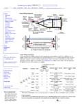
10 UNESCO EOLSSSAMPLE CHAPTERSHYDRAULIC STRUCTURES, EQUIPMENT AND WATER DATA ACQUISITION SYSTEMS Vol. III - Design of Spillways and Outlet Works for Dams - Shand Encyclopedia of Life Support Systems (EOLSS) The choice of a spillway type depends on a number of factors including the dam type, topography, geology, flood discharge and the frequency and duration of overflows. The main components of Spillways influenced by these factors and which have to be combined in the most economically effective manner are the following as shown in Figure 1: the entrance tunnel the control structure the discharge carrier the energy dissipater the Outlet channel Figure 1: Spillway Components Equations in subsequent sections are in metric units.
