Transcription of DESIGNING STEAM JET VACUUM SYSTEMS - Graham …
1 DESIGNING STEAM JET VACUUM SYSTEMSFor cost-effective VACUUM pumping, the proper placement of condensers and pipe supports are criticalDAVID B. BIRGENHEIER AND THOMAS L. BUTZBACH, Graham Manufacturing Company, E. BOLT, Foster Wheeler Energy K. BHATNAGAR, Nash-Kenema, E. OJALA, Croll-Reynolds, AGLITZ, Nitech, VACUUM SYSTEMS combine ejectors, con-densers and interconnecting piping to providerelatively low-cost and low-maintenance vacuumpumping. These SYSTEMS operate on the ejector-ven-turi principle, which relies on the momentum of ahigh-velocity jet of STEAM to move air and other gasesfrom a connecting pipe or system design, critical decisions must bemade regarding process conditions, component ori-entation and layout.
2 A reliable source of STEAM andcooling water must be available, and provisions mustbe made to carry out condensate removal under VACUUM . Finally,the appropriate monitoring and control instrumentation must bespecified. Specific guidelines should be followed during equip-ment layout and installation, to optimize system ejector is a type of VACUUM pump or an ejector has no valves, rotors, pistons or other movingparts, it is a relatively low-cost component is easy to operate andrequires relatively little a STEAM -jet ejector, the suction chamber is connected to thevessel or pipeline that is to be evacuated under VACUUM . The gasthat is to be induced into the suction chamber can be any fluidthat is compatible with the STEAM and the components materialsof STEAM nozzle discharges a high-velocity jet across the suctionchamber.
3 This STEAM jet creates a VACUUM which extracts air or gasfrom the adjoining vessel. As these gases are entrained in thesteam, the mixture travels through the ejector into a venturi-shaped diffuser. In the diffuser, its velocity energy is convertedinto pressure energy, which helps to discharge the mixture againsta predetermined back pressure, either to atmosphere or to a con-denser (Figure 1).Since the capacity of a single ejector is fixed by its dimensions, asingle unit has practical limits on the total compression andthroughput it can deliver. For greater compression, two or moreejectors can be arranged in series. For greater throughput capacityof gas or vapor, two or more ejectors can be arranged in a multi-stage system , condensers are typically used betweensuccessive ejectors.
4 By condensing the vapors before sending thestream on to the next stage, the vapor load is reduced. This allowssmaller ejectors to be used, and reduces STEAM can be added to reduce the load on the first-stageejector, and allow for a smaller unit. An aftercondenser can alsobe added, to condense vapors from the final stage. Adding anaftercondenser will not affect overall system performance, butmay ease disposal of may be installed at any angle. However, to keep conden-sate and any entrained solids from collecting, low points in thevacuum piping system should be avoided during design should be made to ensure proper drainage of the ejec-tor bodies, since any condensed STEAM or process vapors mayreduce throughput capacity.
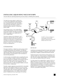
5 Drain valves installed at low pointscan be either manual or automatic, depending on customerrequirements, and the drain cycle must relate to the type ofprocess: Batch SYSTEMS should be drained before each cycle, whilecontinuous processes may be drained during operation if most cases, the ejector is an integral part of a STEAM -jet vacuumsystem, but it is not intended to provide physical support for thesystem. Adequate piping support should be provided to minimizeexternal loads on the ejectors, since any misalignment willadversely affect system performance. In fact, care must be exer-Reprinted from Chemical Engineering, July 19931 Figure 1. In a basic ejector assembly, high-velocity STEAM drawnthrough a nozzle creates a VACUUM , which creates suction to evacuatea connected vessel or pipeline.
6 The STEAM mixes with evacuated airor vapors, and the stream is discharged through a during system design, so that external loadscaused by thermal movement and mechanical load-ing are the ejector or piping is STEAM jacketed to preventice buildup, its orientation will affect the operationand drainage of the jackets. To keep the jacketsfrom filling with condensate, all inlet and outletpiping should be installed so that the jacket can besufficiently certain SYSTEMS , VACUUM processes produce vary-ing amounts of solid carryover, which can depositinside the ejector system . During ejector placement,access for cleaning must be maintained, especially ifthe potential for deposits In multi-stage SYSTEMS , intercondensersare used between successive ejector stages to reducethe vapor load on later stages.
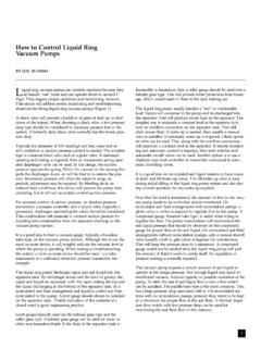
7 These units condensesteam and condensable vapors, and cool air andother non-condensable vapors. Typically, a STEAM -jet VACUUM sys-tem uses either a direct-contact (or barometric) condenser, or asurface condenser, typically a shell-and-tube heat optimal performance, direct-contact condensers must beinstalled upright and plumb. When the condenser is mounted atbarometric elevation (Table, ), drainage by gravity isinduced through a sealed tailpipe or drainage leg. Such a con-denser must be placed at a height that is sufficient to preventflooding under normal operation. Water inlet and outlet pipingmust be sized according to design a direct-contact condenser, the drainage lines or tailpipesshould be installed vertically, and should run to a hotwell or sealtank (Figure 2).
8 All tailpipes connected to inter- and aftercon-densers must run separately to the hotwell to preventrecirculation of non-condensable vapors. Condensate removal isdiscussed surface condensers may be installed either hori-zontally or vertically. The vapors to be condensed can be routedthrough either the inside or the outside of the tubes. However,once a unit has been designated for tubeside or shellside vaporduty, it should remain dedicated to that type of condenser must be installed to allow for complete conden-sate drainage. Mounting arrangements should take into accountthe weight of the condenser when it is fully of the Heat Exchange Institute sStandards for STEAM Jet VACUUM SYSTEMS (4th ed.)
9 Details the pro-cedure for calculating pressure drop in VACUUM SYSTEMS . Ingeneral, the diameter of the piping between the process and theejector system must be at least as large as the suction connectionin the first-stage ejector. In a multiple-element ejector system ,where the ejectors may be operated simultaneously, the pipingarea must be at least as large as the total cross-sectional area,which is determined by adding the total areas of all ejector minimize pressure drop, all piping between the process andthe STEAM -jet VACUUM system and between each successivestage of the VACUUM system should have as few valves and fit-tings as possible, and all connections should be kept as short aspossible.
10 Wherever possible, long-radius elbows should be used,and drains must be provided in all low points to prevent conden-sate a precondenser is used, the potential pressure drop across itmust be calculated, to ensure that such pressure drop will notimpede system performance. The ejector manufacturer should beconsulted to determine the suitability of the supply. A source of dry STEAM at or slightly above designpressures - must be available at the ejector nozzles at all a STEAM -jet VACUUM system at STEAM pressures lower thanthose specified in the system design will reduce system STEAM should be dry and saturated, unless the system specifi-cations call for superheated STEAM .