Transcription of Desuperheater - Graham
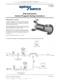
1 IOM-DSH-0209. Desuperheater Installation, Operation &Maintenance Manual Graham Corporation 20 Florence Avenue Batavia, New York 14020. Email: Phone: 585-343-2216 Fax: 585-343-1097. TABLE OF CONTENTS. SECTION I - GENERAL INFORMATION ..3. Introduction ..3. Principle of Control ..3. Design Mechanical SECTION II - INSTALLATION ..5. Initial Inspection ..5. SECTION III - OPERATION ..6. Start-Up ..6. SECTION IV - TROUBLESHOOTING ..7. General Analysis ..7. SECTION V - OPERATOR'S MAINTENANCE ..7. Desuperheater Recommended Inspection ..7. SECTION VI - REPAIR AND REPLACEMENT ORDERS ..8. Figure Figure II ..10. Figure Figure IV ..12. Figure 2. SECTION I - GENERAL INFORMATION. Introduction Most Desuperheater applications reduce the temperature of steam generated by high pressure/high temperature boilers to levels required in process operations. The primary function of a Desuperheater is to lower the temperature of superheated steam or other vapors. This temperature reduction is accomplished as a result of the process vapor being brought into direct contact with another liquid such as water.
2 The injected water is then evaporated. The two main reasons for lowering the steam or vapor temperatures are: (1) to permit operation of downstream process equipment that is designed for lower temperatures, and (2) to maintain a constant temperature for processes that require precise temperature control. Principle of Operation All desuperheaters operate on the same principle. Water (usually condensate), is introduced into the process line and thus comes into direct contact with the superheated steam. Evaporation of the water reduces the steam temperature. The outlet steam temperature is controlled by the quantity of water that is evaporated. It is preferred to use hot injection water near the saturation temperature of the steam to be cooled so that it is mainly the latent heat which is extracted to evaporate the injection water. This minimizes the time of the suspension of the water particles in the steam so that all the water is evaporated and none falls to the inside walls of the pipe work.
3 Control For good control, outlet steam temperature must maintain a minimum of 10 degrees F. superheat. Generally, as the amount of superheat in outlet steam is increased, the easier it becomes to maintain temperature control. Most Desuperheater applications require that the unit operates over a range of superheated steam flows. The ratio of the maximum flow required to the minimum flow that accurate temperature control can be maintained is known as the capacity turndown. As an example, if a Desuperheater is designed to operate at a maximum flow of 50,000#/hr., and a minimum flow of 5,000#/hr., then turndown is 10:1. The turndown is a function of the line velocity. The minimum controllable flow creates the lowest velocity that can suspend the water droplets until they are evaporated. It is important that the user not specify higher turndown than their process actually requires. This will increase cost and reduce efficiency. Also, steam outlet temperatures should 3.
4 Not be controlled any lower than is necessary, since more precise control can be obtained with higher residual temperatures and water is evaporated more easily. For accurate control, it is important that the temperature sensing element be properly placed. The sensor should be far enough downstream to allow for complete evaporation of the water, yet not so far that a time lag is created in the control systems response to temperature change. This is usually 30 feet downstream of the unit. Design Description The two types of desuperheaters manufactured by Graham are the venturi (SV) type and the steam atomizing (SA) type. The SV type has two variations - the SV-1 and the SV- 2. In both types, water is supplied at the water injection venturi throat where it becomes atomized by the accelerated steam flow. The SV-1 incorporates a second larger venturi (diffuser or mixing venturi) that allows for greater turndown and closer approach than the SV-2. In addition, the water inlet on the SV-1 has a special thermal sleeve to minimize thermal stresses.
5 This thermal sleeve may or may not be supplied on the SV- 2 type The SA type offers a greater turndown than either of the SV type desuperheaters . The SA type uses higher pressure steam (a minimum of times the line pressure) to atomize the water. The amount of atomizing steam required is a small percentage (usually 1% - 2%) of the superheated steam flow. A dropout pot may be required downstream of the SA Desuperheater if flows get so low that the decrease in velocity causes some of the water droplets to fall out of suspension. Mechanical Description Desuperheater bodies are manufactured in carbon steel up to a design temperature of 800 degrees F. Above this temperature a grade of chrome molybdenum steel is used. The desuperheating element is usually stainless steel, but at times it may be necessary to use a grade of chrome-moly. Other body materials such as stainless steel are also available. The SV-2 type desuperheaters have the most simple construction.
6 The SV-2 style (see Figures No. I and II) consists of either a ring that is clamped in between two line flanges, or a pipe with either flanged or welded ends. A water injection venturi is located concentrically within the ring or pipe, with the water supply line entering the ring/pipe at a right angle and welded to the venturi throat. The throat has a drilled hole that is sized to pass the required desuperheating water with minimum pressure drop. This unit is limited to cooling the steam to within 20 degrees F of saturation. 4. The SV-1 style is basically similar to the SV-2, with the exception that a second larger venturi (diffuser or mixing venturi) is welded to the end of the pipe (see Figure III). This is the only type where we have a pressure drop through the unit. It is capable of cooling to within 10 degrees F of saturation and a greater turndown can be obtained than with the SV-2 type. A variation of the SV-1 consists of the mixing venturi and water injection venturi located within a pipe that has a high pressure design.
7 (Figure IV). The SA type consists of a pipe with either flanged or welded ends (see Figure V). Located within the pipe is the desuperheating head which contains the high pressure steam nozzle and the cooling water orifices. The atomizing steam and water supply lines enter the Desuperheater pipe at right angles and are welded to both the pipe and the head. A variation of the SA type, the "T" mount style (see Figure V, dotted portion), consists of a blind flange through which the atomizing steam and water lines enter at right angles. The flange is connected to a tee in the superheated steam line. The head is located at such a distance from the flange that it becomes centered in the steam line. With the SA style, water can be broken down to finer droplets improving performance and obtaining greater turndown ratios. SECTION II - INSTALLATION. Initial Inspection Inspect for shipping damage to all protective covers: If damage is evident, inspect for internal contamination and replace protective covers if the unit is going to be stored.
8 If unit is damaged physically, notify the carrier immediately and then contact Graham Corporation. Installation Both the venturi type and steam atomizing type of desuperheaters are installed directly in the steam line. Orientation may be in either a horizontal or vertical up position. In instances where a pressure reducing valve is installed upstream of the Desuperheater , the nominal distance of the valve from the Desuperheater inlet should be five (5) pipe diameters. The water valve should be installed as close to the Desuperheater as is practical. 5. For temperature control down to 10 degrees F superheat, the minimum distance of the temperature sensing element is 30 ft. downstream of the Desuperheater . Elbows may be inserted in between the Desuperheater and the sensor. Straight pipe before the first elbow should be equal to 10% of the maximum steam line velocity. If the steam line velocity is 150 ft/sec then there should be 15 feet to the first elbow.
9 If the residual superheat is greater than 10 degrees F, Graham still recommends that the sensing element be placed 30 ft. downstream. However, if the residual amount of superheat is substantial enough, the distance of the sensor may be somewhat less than 30 ft. For such specific applications, Graham Corporation should be consulted for proper sensor placement. The sensing element itself should be completely immersed in the steam line, and the thermometer well should be designed so as to insure an ample rate of heat transfer. A slow rate of heat transfer from the well to the element can cause a serious measurement time lag. If the Desuperheater is a steam atomizing type, and the required turndown is such that line velocity may at times be lower than 50 , then a dropout pot with a trap or an on/off valve may be installed to remove excess water. The pot should be one-half the diameter of the nominal line size and located 10-15 ft. downstream of the Desuperheater .
10 Check with the manufacturer for proper installation of the control apparatus. SECTION III - OPERATION. Start-Up A. Manual Operation 1) Drain steam line before main steam pressure reducing valve, if used, as well as the Desuperheater line. 2) For SA type only .. open atomizing steam valve fully, cracking the water valve at the same time. Note that the atomizing steam flow is constant, and cannot be throttled with the water flow. 3) Open main steam valve, increasing flow slowly. The water flow should be increased at the same time if desuperheating is desired during the start-up. 4) When desired steam flow is reached, adjust water valve to give the desired discharge steam temperature. B. Automatic Operation 1) Open all stop valves. 2) Follow instructions for manual start up omitting step #2. 3) Set control apparatus per instruction provided by the manufacturer. 6. Shutdown 1) Shut off steam flow with main steam valve. 2) If SA type, close the atomizing steam valve.
