Transcription of Differential Protection of EAF Transformers …
1 Differential Protection COIL. rogowski Time A. Designs Rb by Ljubomir Kojovic and Martin Bishop, Cooper Power Systems ,USA. 36 37. Protection of EAF Transformers L. Tap Position C. B. EAF. Transformers "Water-Cooled". Conductors EAF. rogowski Coil can replace CTs for Protection , metering, and control purposes. rogowski coils are accurate, small, light, and easy to install. They do not saturate. rogowski coils provide superior Differential Protection for power Transformers , substation busbars, generators, and large motors. rogowski coils make it possible to set This article presents advanced relay Protection systems Protection levels to lower fault that incorporate rogowski Coil current sensors and multifunction relays. rogowski coils are accurate and do not saturate, making it possible to set current thresholds (increased Protection levels to lower fault current thresholds (increased sensitivity of the scheme) while preserving high stability of the scheme for through sensitivity of the scheme) while faults.
2 This reduces the stress on the protected equipment during faults. Even though rogowski coils are low power sensors, the Protection system preserving high stability of the is immune to external electromagnetic fields. The schemes are simple, user friendly and require less wiring and space than conventional solutions. scheme for Out-Of-Zone faults. The rogowski coil (RC) current sensors presented here operate on the same principle as coils that were first introduced in 1912 for magnetic field measurements. At that time, the coils could not be used for relay Protection because their output power was not sufficient to drive electro- by Ljubomir Kojovic and Martin Bishop, Cooper Power Systems ,USA. 38. 38. mechanical relays. However, with today's microprocessor- use such signals with phasor-based protective relays, signal Protection based equipment, RC current sensors are suitable for such processing is required to extract the power frequency signal.
3 Applications. Current Transformers have traditionally been used for Protection and measurement applications, in part because of their ability to produce the high power output (1). needed by electromechanical equipment. Microprocessor- based equipment makes high power output unnecessary. This article presents novel solutions for Differential This may be achieved using one of the following methods: Protection of power Transformers , busbars, generators, (a)-integrating the rogowski Coil output signal, or (b)-using and large motors. The initial projects included Differential a non-integrated signal and perform signal processing to Protection of EAF Transformers , which are the first such adjust magnitudes and phase shift signals 90 . For an ideal rogowski Coil applications in the and most likely in the world. RC, measurement accuracy is independent of conductor location inside the coil loop.
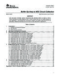
4 See Figure 2. rogowski Coil Principle of Operation To prevent the unwanted influence of nearby conductors For comparative analysis of rogowski coils and iron- carrying high currents, RCs are designed with two wire core current Transformers (CTs), equivalent circuits and loops connected in electrically opposite directions. This vector diagrams for resistive load are shown in Figure 1. cancels electromagnetic fields coming from outside the coil The CT is a non-linear element that saturates whenever flux loop. One or both loops can consist of wound wire. If only inside the CT core exceeds the saturation level, resulting in one loop is constructed as a winding on a non-magnetic Ljubomir Kolovic distorted and reduced secondary current that may cause relay core, then the second wire loop can be constructed by is a Chief Power misoperation.
5 However, CTs cannot saturate immediately returning the wire through or near this winding. If both Systems Engineer upon the fault inception. The time that it takes to begin the loops are constructed as windings, then they must be wound for Cooper Power CT saturation is called time-to-saturation. Manufacturers in opposite directions. In this way, the RC output voltage Systems at the use different algorithms to achieve proper relay performance induced by currents from the inside conductor(s) will be Thomas A. Edison during the CT saturation or design relays to operate prior to doubled. rogowski coils can also be connected in series to Technical Center. the CT saturation. Remanent flux in the CT core can also increase the output signal. He has a in cause relay misoperation. To reduce remanent flux, gapped- Influence from nearby conductors is one of the most power systems, core CTs have been used.
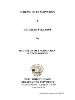
6 Important tests to determine the RC current sensor accuracy. including protective Traditional RCs consist of a wire wound on a non- The test was performed in a high power laboratory at a test relaying, distributed magnetic core. The coil is then placed around conductors current magnitude of 60 kARMS (Figure 4). Two RC current generation, testing, whose currents are to be measured. The output voltage sensors were tested, RC1 was installed to measure the test digital modeling, is proportional to the rate of change of measured current current and RC2 was located next to the primary conductor and systems (Equation 1) where is the magnetic permeability of air, n to test the influence from the primary conductor. Since analysis. He is an is the winding density (turns per unit length), S is the core the induced signal in RC2 was very small, a x100 amplifier adjunct assistant cross-section, and M is the mutual coupling.
7 Was used to increase the signal to the level acceptable to the professor at Michi- A rogowski Coil signal is a scaled time derivative, recorder. The influence from the primary conductor was gan Technological di(t)/dt of the primary current instantaneous signal. To below , verifying very good coil immunity to the University, Senior Member of the IEEE. PES, member of the IEEE Power System 1 Current Transformer and rogowski Coil Circuits & Vector Diagrams Relaying Commit- M. tee, and member of Ip I'p Rs IS Ip Ls Rs Is CIGRE. Dr Kojovic is a Technical Advisor for the US National vs vB RB vs vB RB. Committee at the IEC TC-38 Instru- Ie ment Transformers . He is a registered RB < 5 RB > 50 k . professional engine- vs er in Wisconsin, has I sR s vB. eight patents ZsIs L SI S. vs Is vB 90. and authored more than 150 technical Ie 90 IS R sIs publications.
8 I'p I'p 39. external magnetic fields. In most applications, RC current schemes and settings are possible. The rogowski Coil Martin Bishop sensors will be installed at a distance from nearby conductors applications for relay Protection presented here include is a Chief Engineer and the influence will be nearly zero. Differential Protection of power Transformers , busbars, in the Systems Performance characteristic comparison between generators, and large motors. Integration Group conventional bushing type iron-core CTs and rogowski of Cooper Power Sy- coils is shown in Table 1. Differential Protection of Power Transformers stems, S. Milwaukee, Figure 5 shows a traditional power transformer Wisconsin. The sec- Designs Differential Protection based on conventional CTs. tion is responsible The high precision rogowski Coil design presented here The Protection Zone is defined by the CT locations.
9 A for projects related consists of two printed circuit boards (PCBs) located next to recognized problem of the CT-based Protection schemes to power systems each other. Each PCB contains one imprinted coil wound in has been the CT saturation. For Out-Of-Zone faults, when Protection and opposite directions (clockwise and counter-clockwise). The the CTs saturate, false Differential current is derived by system applications. top and bottom sides of each PCB are imprinted to form a the relay, which can cause unwanted relay operation (lack Marty is responsible coil around the center of the board. The conductive imprints of stability). Manufacturers use different algorithms to for the marketing on the upper and lower sides of the PCB are interconnected achieve proper relay performance during the CT saturation and engineering by conductive-plated holes.
10 High precision is obtained or they may design relays to operate prior to the CT development of because the manufacturing process is computer controlled, saturation. Remanent flux in the CT core can also cause relay relay Protection providing accurate geometry of the coils . New RC designs misoperation. rogowski coils are linear and will not have systems. He has use multi-layer PCBs, which provides for higher accuracy remanence. This allows for improved relay performance or served as an instru- and more efficient manufacturing. even Protection scheme development that was not possible ctor in many Cooper PCB rogowski coils can be designed with different using CTs (such as Differential Protection of electric arc Power Systems'. shapes to adjust for the application and in split-core styles furnace Transformers ).