Transcription of Digital Valve Controllers - Cotswold Valves
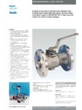
1 Series FIELDVUER Digital ValveControllersDVC6000 Series FIELDVUER Digital valvecontrollers (figures 1 and 2) are communicating,microprocessor-based current-to-pneumaticinstruments. In addition to the traditional function ofconverting a current signal to a Valve -positionpressure signal, DVC6000 Series Digital valvecontrollers, using HARTR communications protocol,give easy access to information critical to processoperation. This can be done using a Model 375 FieldCommunicator at the Valve or at a field junction box,or by using a personal computer or a systemconsole within the control room. Using HART communication protocol, information can beintegrated into a control system or received on asingle loop Series Digital Valve Controllers can beused on single- or double-acting actuators. Thedigital Valve controller receives feedback of the valvetravel position plus supply and actuator pneumaticpressure.
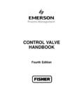
2 This allows the instrument to diagnoseW7957-1 / ILFigure 1. Type DVC6010 Digital Valve controller Mounted ona Sliding-Stem Valve Actuatornot only itself, but also the Valve and actuator towhich it is mounted. This provides you with very costeffective maintenance information, as the requiredmaintenance can be performed on the instrumentand Valve when there really is a is economical because DVC6000 Seriesdigital Valve Controllers use two-wire 4 to 20 mA looppower. This provides for low cost replacement ofexisting analog instrumentation. The DVC6000 Series Digital Valve controller s two-wire designavoids the high cost of running separate power andsignal Emerson, Emerson ProcessManagement, nor any of their affiliatedentities assumes responsibility for theselection, use and maintenance of anyproduct. Responsibility for theselection, use and maintenance of anyproduct remains with the purchaserand 2.
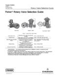
3 Type DVC6010 Digital Valve controller Mounted onType 585C Piston ActuatorProduct :DVC6000 April 2007 DVC6000 SeriesDVC6000 SeriesProduct :DVC6000 April 2007 2 SpecificationsAvailable ConfigurationsValve-Mounted Instrument:DVC6010: Sliding-stem applicationsDVC6020: Rotary applications and long-strokesliding-stem applicationsDVC6030: Quarter-turn rotary applicationsRemote-Mounted Instrument(1):DVC6005: Base unit for 2-inch pipestand or wallmountingDVC6015: Feedback unit for sliding-stemapplicationsDVC6025: Feedback unit for rotary or long-strokesliding-stem applicationsDVC6035: Feedback unit for quarter-turn rotaryapplicationsDVC6000 Series Digital Valve Controllers can bemounted on fisher and other manufacturersrotary and sliding-stem Signal(2)Point-to-Point:.Analog Input Signal: 4 20 mA DC, nominal; splitranging availableMinimum Voltage Available at InstrumentTerminals must be VDC for analog control,11 VDC for HART communication (see instrumentinstruction manual for details)Minimum Control Current: mAMinimum Current w/o Microprocessor Restart: Voltage: 30 VDCO vercurrent Protection: Input circuitry limitscurrent to prevent internal damageReverse Polarity Protection: No damage occursfrom reversal of loop currentMulti-drop.
4 Instrument Power: 11 to 30 VDC at approximately 8 mAReverse Polarity Protection: No damage occursfrom reversal of loop currentOutput Signal(2)Pneumatic signal as required by the actuator, upto 95% of supply pressureMinimum Span: bar (6 psig)Maximum Span: bar (140 psig)Action: JDouble, JSingle Direct, and JSingleReverseSupply Pressure(3)Minimum Recommended: bar (5 psig)higher than maximum actuator requirementsMaximum: bar (145 psig) or maximumpressure rating of the actuator, whichever is lowerSteady-State Air Consumption(4,5)Standard Relay:At bar (20 psig) supply pressure: Less normal m3/hr (14 scfh)At bar (80 psig) supply pressure: Less normal m3/hr (49 scfh)Low Bleed Relay(6):At bar (20 psig) supply pressure: Averagevalue normal m3/hr ( scfh)At bar (80 psig) supply pressure: Averagevalue normal m3/hr ( scfh)Maximum Output Capacity(4,5)At bar (20 psig) supply pressure: normalm3/hr (375 scfh)At bar (80 psig) supply pressure: normalm3/hr (1100 scfh)Independent Linearity(2,7) of output spanElectromagnetic Interference (EMI)Tested per IEC 61326-1 (Edition ).
5 Meetsemission levels for Class A equipment (industriallocations) and Class B equipment (domesticlocations). Meets immunity requirements forindustrial locations (Table in the IECspecification document). Immunity performance isshown in table 61010 Compliance Requirements( Valve -Mounted Instruments Only)Power Source: The loop current must be derivedfrom a separated extra-low voltage (SELV) powersourceEnvironmental Conditions: Installation Category I(continued)DVC6000 SeriesProduct :DVC6000 April 2007 3 Specifications (continued)Electrical ClassificationHazardous Area: Explosion proof, Division 2, Dust-Ignition proof, Intrinsically Safe Explosion proof, Non-incendive, Dust-Ignition proof, Intrinsic Safety Flameproof, Type n, Intrinsic Safety Flameproof, Type n, Intrinsic Safety Flameproof, Intrinsic SafetyRefer to tables 3, 4, 5, 6, and 7 for specificapproval informationElectrical Housing: Meets NEMA 4X, CSA Type4X, IEC 60529 IP66 ConnectionsSupply Pressure: 1/4 NPT internal and integralpad for mounting 67 CFR regulatorOutput Pressure.
6 1/4 NPT internalTubing: 3/8-inch metal, recommendedVent (pipe-away): 3/8 NPT internalElectrical: 1/2 NPT internal conduit M20 internal conduit connection,spring clamp terminal connection(8)Operating Ambient Temperature Limits(3) 40 to 80_C ( 40 to 176_F) for most approvedvalve-mounted instruments 60 to 125_C ( 76 to 257_F) for remote-mountedfeedback unit. 52 to 80_C ( 62 to 176_F) for Valve -mountedinstruments utilizing the Extreme Temperatureoption (fluorosilicone elastomers).Construction MaterialsHousing, module base and terminal box:ASTM B85 A03600 low copper aluminum alloy(standard)CF8M (cast 316 stainless steel) (optional forvalve-mounted instruments only)Cover: Thermoplastic polyesterElastomersStandard: Nitrile Optional: FluorosiliconeStem TravelDVC6010, DVC6015:0 to 102 mm (4 inches) maximum travel span0 to mm (3/8 inches) minimum travel spanDVC6020, DVC6025: 0 to 606 mm (23-7/8inches) maximum travel spanShaft Rotation (DVC6020, DVC6025, DVC6030and DVC6035)0 to 50 degrees minimum0 to 90 degrees maximumMountingDesigned for direct actuator mounting or remotepipestand or wall mounting.
7 Mounting theinstrument vertically, with the vent at the bottomof the assembly, or horizontally, with the ventpointing down, is recommended to allow drainageof moisture that may be introduced via theinstrument air : kg ( lbs)Stainless steel: kg (17 lbs)Remote-Mounted Base Unit: kg (9 lbs)DVC6015 Feedback Unit: kg ( lbs)DVC6025 Feedback Unit: kg ( lbs)DVC6035 Feedback Unit: kg ( lbs)OptionsJSupply and output pressure gauges or JTirevalves, JIntegral mounted filter regulator,J Stainless steel housing, module base andterminal box ( Valve -mounted instruments only),JLow-Bleed Relay, JExtreme Temperature1. 3-conductor shielded cable, 22 AWG minimum wire size, is recommended for connection between base unit and feedback unit. Pneumatic tubing between base unit output connection andactuator has been tested to 15 meters (50 feet) maximum without performance These terms are defined in ISA Standard The pressure/temperature limits in this document and any other applicable code or standard should not be Normal m3/hour Normal cubic meters per hour at 0_C and bar, absolute.
8 Scfh Standard cubic feet per hour at 60_F and Values at bar (20 psig) based on a single-acting direct relay; values at bar (80 psig) based on double-acting The Low Bleed Relay is offered as standard relay for DVC6000 SIS tier, used for On/Off Typical value. Not applicable for DVC6020 Digital Valve Controllers in long-stroke applications or remote-mounted DVC6005 Digital Valve Controllers with long pneumatic tubing ATEX/IEC approvals SeriesProduct :DVC6000 April 2007 4 Table 1. DVC6000 Product Level CapabilitiesCAPABILITYDIAGNOSTIC TIER LEVELACHCADPDSIS(1)ODVAuto CalibrationXXXXXXB urst CommunicationXXXXXC ustom CharacterizationXXXXXXA lertsXXXXXStep Response, Drive Signal Test &Dynamic Error Band, Valve SignatureXXXXP erformance TunerXXXXT ravel Control Pressure FallbackXXXP erformance DiagnosticsXXPartial Stroke TestingXXLead/Lag Input Filter(2)X1.
9 Refer to Bulletin :DVC6000 SIS for information on DVC6000 Series FIELDVUER Digital Valve Controllers for Safety Instrumented System (SIS) Refer to brochure part # D351146X012 / D351146X412 for information on fisher optimized Digital Valves for compressor antisurge Control Two-way digitalcommunications give you current Valve can rely on this real-time information to makesound process management decisions. By analyzingvalve dynamics through AMSt ValveLinkR Softwareyou can identify control areas needing improvementand maintain a high level of system Protection You can avoidadditional field wiring by connecting a leak detectoror limit switch to the auxiliary terminals in theDVC6000 Series Digital Valve controller . In this way,the instrument will issue an alert if limits Safety You can check instrumentand Valve operation and keep the process runningsmoothly and safely from a remote location.
10 Accessis possible at a field junction box, marshalling panel,or within the safety of the control room using either a375 Field Communicator, a notebook PC, or asystem workstation. Your exposure to hazardousenvironments is minimized and you can avoid havingto access hard-to-reach Valve Savings DVC6000 Series digitalvalve Controllers , when used in an integratedsystem, allow you to realize significant hardware andinstallation cost savings by replacing other devicesin the process loop, such as positioners and limitswitches, with a FIELDVUE Digital Valve to Survive Field-tough DVC6000 Seriesdigital Valve Controllers have fully encapsulatedprinted wiring boards that resist the effects ofvibration, temperature, and corrosive separate weather-tight field wiring terminal boxisolates field-wiring connections from other areas ofthe Uptime With the self-diagnosticcapability of DVC6000 Series Digital valvecontrollers, you can answer questions about avalve s performance, without pulling the Valve fromthe line.