Transcription of Dimensioning, Gaging, and Measuring
1 TABLE OF CONTENTS629 DRAFTING PRACTICES630 ANSI Drafting Practices630 Sizes of Drawing Sheets630 Symbols for Section Lining 630 geometric Dimensioning633 ANSI and ISO Symbols634 Definitions638 Datum Referencing640 Positional Tolerance642 Checking DrawingsALLOWANCES AND TOLERANCES FOR FITS645 Basic Dimensions645 Tolerances647 Force fits648 Expansion and Shrinkage Fits649 Temperatures for Shrinkage Fits651 ANSI Standard Limits and Fits651 Definitions652 Preferred Basic Sizes652 Standard Tolerances652 ANSI Standard Fits656 Modified Standard Fits658 Running and Sliding Fits 660 Clearance Locational Fits662 Transition Locational Fits 665 ANSI Metric Limits and Fits665 Definitions666 Tolerances Designation667 Preferred Metric Fits670 Hole Basis Fits670 Clearance Fits672 Transition and Interference Fits674 Shaft Basis Fits674 Clearance Fits676 Transition and Interference Fits 678 Gagemakers Tolerances 679 ISO Metric Limits and Fits680 Definitions680 Calculated Limits of Tolerance682 Tolerance for Selected Holes 682 Tolerance for Selected Shafts 683 Clearances 685 Deviations for Shafts 687 Deviations for Holes 689 Preferred Numbers689 ANSI Preferred Numbers690 Preferred Metric SizesMEASURING INSTRUMENTS AND INSPECTION METHODS692 Verniers and Micrometers693 Dual Metric-Inch Vernier695 Metric Micrometer695 Sine-bar695 Types of Sine-bars696 Setting a Sine-bar697 Using Sine-bar Tables698 Measuring Tapers with V-block698 dimensioning Tapers699 Constants for 5-inch Sine-bar706 Constants for 100-mm Sine-bar713 Angles and Tapers713 Measuring Dovetail Slides714 Tapers per Foot 715 Figuring Tapers717 Measurement over Pins and Rolls717 Measurement over Pins717 Checking a V-shaped Groove718 Checking Radius of Arc719 Checking Shaft Conditions721 Out-of-Roundness and Lobing723 Measurements Using LightSURFACE TEXTURE724 ANSI Surface
2 Texture726 Definitions727 Sampling Lengths728 Roughness Parameters729 Waviness Parameters729 Surface Roughness to Tolerances730 Instruments for Measurement731 Roughness Measurements731 Surface Texture Symbols734 Roughness Average Values735 Lay Symbols735 Surface Texture of Castings735 Metric Dimensions on Drawings738 ISO Surface Finish738 Surface Finish Symbology740 Roughness Lengths743 Gage Blocks743 Precision Gage Blocks744 Gage Block SetsDIMENSIONING, GAGING, AND MEASURINGM achinery's Handbook 27th EditionCopyright 2004, Industrial Press, Inc., New York, NY630 dimensioning , GAGING, AND MEASURINGDRAFTING PRACTICESA merican National Standard Drafting PracticesSeveral American National Standards for use in preparing engineering drawings andrelated documents are referred to for of Drawing Sheets. Recommended trimmed sheet sizes, based on ANSI (R1987), are shown in the following standard sizes shown by the left-hand section of the table are based on the dimen-sions of the commercial letter head, 81 2 11 inches, in general use in the United States.
3 Theuse of the basic sheet size 81 2 11 inches and its multiples permits filing of small tracingsand folded blueprints in commercial standard letter files with or without sheet sizes also cut without unnecessary waste from the present 36-inch rolls ofpaper and drawings made in the metric system of units or for foreign correspondence, it is rec-ommended that the metric standard trimmed sheet sizes be used. (Right-hand section oftable.) These sizes are based on the width-to-length ratio of 1 to .Line Conventions and Drawings. American National Standard (R1987) establishes line and lettering practices for engineering drawings. The line conven-tions and the symbols for section lining are as shown on Tables 1 and width of THICK lines for metric drawings are mm, and for inch draw-ings, inch. Approximate width of THIN lines for metric drawings are mm, andfor inch drawings, inch. These approximate line widths are intended to differentiatebetween THICK and THIN lines and are not values for control of acceptance or rejectionof the Symbols.
4 A detailed explanation of the use of surface-texture sym-bols from American National Standard begins on dimensioning and tolerancing . ANSI/ASME , Dimen-sioning and tolerancing , covers dimensioning , tolerancing , and similar practices forengineering drawings and related documentation. The mathematical definitions of dimen-sioning and tolerancing principles are given in the standard ISO standards ISO 8015 and ISO 26921 contain a detailed explanation ofISO geometric dimensioning and tolerancing dimensioning and tolerancing provides a comprehensive system for sym-bolically defining the geometrical tolerance zone within which features must be provides an accurate transmission of design specifications among the three primaryusers of engineering drawings; design, manufacturing and quality techniques introduced in ANSI/ASME have been accepted by techniques include projected tolerance zone, three-plane datum concept, totalrunout tolerance, multiple datums, and datum targets.
5 Although this Standard follows ISOpractice closely, there are still differences between ISO and practice. (A comparisonof the symbols used in ISO standards and is given on page633.)Size, inchesMetric Size, mmA81 2 11D22 34A0841 1189A3297 420B11 17E34 44A1594 841A4210 297C17 22F28 40A2420 5942 Machinery's Handbook 27th EditionCopyright 2004, Industrial Press, Inc., New York, NYDRAFTING PRACTICES631 Table 1. American National Standard for Engineering Drawings ANSI/ASME LineHidden LineSection LineCenter LineSymmetry LineDimensionLineExtensionLineAnd LeaderCutting-PlaneLine orViewing-PlaneLineBreak LinePhantom LineStitch LineChain LineTHICKTHINTHINTHINTHINTHINL eaderExtension LineDimension BreaksTHICKTHINS hort BreaksTHINTHIN..THINTHICKM achinery's Handbook 27th EditionCopyright 2004, Industrial Press, Inc., New York, NY632 DRAFTING PRACTICEST able 2. American National Standard Symbols for Section Lining ANSI (R1987)Cast and Malleable iron (Also for gen-eral use of all mate-rials)Titanium and refrac-tory materialSteelElectric windings, electro magnets, resistance, , brass, cop-per, and composi-tionsConcreteWhite metal, zinc, lead, babbitt, and alloysMarble, slate, glass, porcelain, , alumi-num, and aluminum alloysEarthRubber, plastic electrical insulationRockCork, felt, fabric, leather, fiberSandSound insulationWater and other liq-uidsThermal insulationWood-across grainWood-with grainMachinery's Handbook 27th EditionCopyright 2004, Industrial Press, Inc.
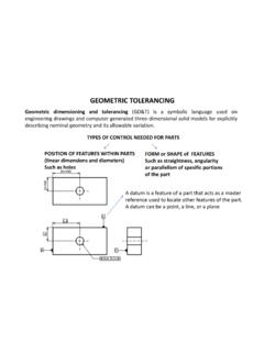
6 , New York, NYGEOMETRIC SYMBOLS633 Table 3. Comparison of ANSI and ISO geometric Symbols ASME forANSI forANSI forANSI Runoutaa Arrowheads may be filled in. Feature Control FrameFlatnessTotal RunoutaDatum FeatureaCircularityAt Maximum Material ConditionAll Around - ProfileCylindricityAt Least Material ConditionConical TaperProfile of a LineRegardless of Feature SizeNONENONES lopeProfile of a SurfaceProjected Tolerance ZoneCounterbore/SpotfaceAngularityDiamet erCountersinkPerpendicularityBasic DimensionDepth/DeepParallelismReference Dimension(50)(50)Square (Shape)PositionDatum TargetDimension Not to Scale1515 Concentricity/Coaxial-ityTarget PointNumber of Times/Places8X8 XSymmetryDimension OriginArc LengthRadiusRRSpherical RadiusSRSRS perical DiameterBetweenaNoneControlled RadiusCRNoneStatical ToleranceNoneMachinery's Handbook 27th EditionCopyright 2004, Industrial Press, Inc., New York, NY634 geometric DIMENSIONINGOne major area of disagreement is the ISO principle of independency versus the Tay-lor principle.
7 And standard practice both follow the Taylor principle, inwhich a geometric tolerancing zone may not extend beyond the boundary (or envelope) ofperfect form at MMC (maximum material condition). This boundary is prescribed to con-trol variations as well as the size of individual features. The definition of indepen-dency further defines features of size as being independent and not required to maintain aperfect relationship with other features. The envelope principle is optional in treatment ofthese principles. A summary of the application of ANSI/ASME geometric control symbolsand their use with basic dimensions and modifiers is given in Table 1. Table 1. Application of geometric Control SymbolsFive types of geometric control, when datums are indicated, when basic dimensions are required,and when MMC and LMC modifiers may be features metric SI units (the International System of Units), butcustomary units may be used without violating any principles.
8 On drawings where alldimensions are either in millimeters or in inches, individual identification of linear units isnot required. However, the drawing should contain a note stating UNLESS OTHERWISESPECIFIED, ALL DIMENSIONS ARE IN MILLIMETERS (or IN INCHES, as applica-ble). According to this Standard, all dimensions are applicable at a temperature of 20 C (68F) unless otherwise specified. Compensation may be made for measurements taken atother units are expressed in degrees and decimals of a degree ( ) or in degrees ( ),minutes ( ), and seconds ( ), as in 35 25 10 . A 90-degree angle is implied where centerlines and depicting features are shown on a drawing at right angles and no angle is speci-fied. A 90-degree BASIC angle applies where center lines of features in a pattern or surfaceshown at right angles on a drawing are located or defined by basic dimensions and no angleis The following terms are defined as their use applies to Feature: The feature of a part that is used to establish a Identifier.
9 The graphic symbol on a drawing used to indicate the datum geometric CharacteristicsPertains ToBasic DimensionsFeature ModifierDatumModifierFormStraightnessONL Y individual featureModifier not applicableNO datumCircularityFlatnessCylindricityProf ileProfile (Line)Individual or relatedYe s i f relatedRFS implied unless MMC or LMC is statedProfile (Surface)OrientationAngularityALWAYS related fea-ture(s)Ye sRFS implied unless MMC or LMC is statedPerpendicularityParallelismLocatio nPositionYesConcentricityOnly RFSOnly RFSS ymmetryRunoutCircular RunoutTotal RunoutMachinery's Handbook 27th EditionCopyright 2004, Industrial Press, Inc., New York, NYGEOMETRIC DIMENSIONING635 Fig. 1. Datum Feature SymbolDatum Plane: The individual theoretical planes of the reference frame derived from aspecified datum feature. A datum is the origin from which the location or other geometriccharacteristics of features of a part are Reference Frame: Sufficient features on a part are chosen to position the part inrelationship to three planes.
10 The three planes are mutually perpendicular and togethercalled the datum reference frame. The planes follow an order of precedence and allow thepart to be immobilized. This immobilization in turn creates measurable relationshipsamong Simulator: Formed by the datum feature contacting a precision surface such as asurface plate, gage surface or by a mandrel contacting the datum. Thus, the plane formedby contact restricts motion and constitutes the specific reference surface from which mea-surements are taken and dimensions verified. The datum simulator is the practical embod-iment of the datum feature during manufacturing and quality assurance. Datum Target: A specified point, line, or area on a part, used to establish a of Freedom: The six directions of movement or translation are called degrees offreedom in a three-dimensional environment. They are up-down, left-right, fore-aft, roll,pitch and 2. Degrees of Freedom (Movement) That Must be Controlled,Depending on the Design B C A control frame and datum identifierLeader may be appropriately directed to a letterA Datum triangle maybe filled or not Combined featureAA A UpDownLeftRight ForeAft Yaw Pitch RollMachinery's Handbook 27th EditionCopyright 2004, Industrial Press, Inc.