Transcription of DIN Panels and Accessories - Lutron Electronics Company Inc
1 Technical Support: +44.(0) Panels and The Lutron family of DIN rail Panels are designed to accept the Lutron DIN power modules (DPMs). The DPMs can be configured in the panel to control multiple load types that fit the size, lighting plan and design of a home. The control Panels have a control gear compartment that can house up to 2 processors, DMX and / or IO interfaces, 2 Wire Landing Boards (WLB), and 1 power supply. The satellite Panels replace the control gear compartment with a mounting bracket to add an additional DPM. Panels may be either surface- mounted or recess- mounted in an electrical closet or other equipment room. There are feed-through, MCB and RCBO breaker options available for each panel size and type. For each DPM type, there is a terminal kit available as well as a wiring harness. There is also a QS harness for wiring from DPM to DPM.
2 Other options include blanking plates for unused module positions and a reversible hinged door. Features Panels house LQSE DIN power modules (DPMs) LQSE-4A-D LQSE-4M-D LQSE-4S10-D LQSE-2 ECO-D LQSE-4T10-D LQSE-2 DAL-D Control Panels support HQP6-2 (HomeWorks QS Processor) QS-WLB QSE-IO QSE-CI-NWK-E QSE-CI-DMX QSPS-DH-1-60 Feed-through, MCB and RCBO breaker Panels available. Panels extensively tested to ensure optimal thermal performance with maximum load in 0 C to 40 C (32 F to 104 F) ambient environment. Schneider Electric commercial grade breakers. Panels with breakers include a main isolation (ISO) switch. Panels with breakers include pre-installed and verified wiring from an ISO switch to breakers. Bypass jumpers included for miswire protection. Panels are rated for 220 240 V~ CE and non-CE applications.
3 Integral manual override switch turns all lights on to the programmed override level when activated. Panels are available in two sizes: 1 613 mm ( in) and 921 mm ( in). Reversible hinged door option available. Terminal Block kits available for each DPM type. Pre-assembled wiring harnesses available for each DPM type. Pre-assembled wiring harness available for QS link from DPM to DPM. Additional live and neutral feeds provided to add breakers in the field for LQSE-2 ECO-D and LQSE-2 DAL-D Support: +44.(0) Panels and NumbersPD10-64-F; PD10-64-BU10-2L4; PD10-64-RU10-2L4; PD10-64-BU10-2L2; PD10-64-RU10-2L2; PD9-64-F; PD9-64-BU10-2L4; PD9-64-RU10-2L4; PD9-64-BU10-2L2; PD9-64-RU10-2L2; PD8-64-F; PD8-64-BU10-2L4; PD8-64-RU10-2L4; PD8-64-BU10-2L2; PD8-64-RU10-2L2;PD5-36-F; PD5-36-BU10-2L4; PD5-36-RU10-2L4; PD5-64-BU10-2L2; PD5-64-RU10-2L2; PD4-36-F; PD4-36-BU10-2L4; PD4-36-RU10-2L4; PD4-64-BU10-2L2; PD4-64-RU10-2L2 PowerFeed-through: 220-240 V~ ; 50 / 60 Hz; 10 A per input maximum.
4 Breaker and RCBO (3 phase 4-wire feed): 220-240 V~ ; 125 A inputBreaker and Feed-through (1 phase, 2-wire feed): 220-240 V~ ; 63 ACapacityPD4-36: Four DPMs * in any combination, two Wire Landing Boards (WLB), one power supply unit and two Interface boxes or processors. The top position supports LQSE-4S10-D module only in MCB and RCBO breaker : Five DPMs * in any combination, two Wire Landing Boards (WLB). The top position supports LQSE-4S10-D module only in MCB and RCBO breaker : Eight DPMs * in any combination, two Wire Landing Boards (WLB), one power supply unit and two Interface boxes or : Nine DPMs * in any combination, two Wire Landing Boards (WLB), one power supply unit and two Interface boxes or processors. The top position supports LQSE-4S10-D module only in MCB and RCBO breaker Panels . PD10-64: Ten DPMs * in any combination, two Wire Landing Boards (WLB).
5 The top position supports LQSE-4S10-D module only in MCB and RCBO breaker A of dimming current maximum in PD9 and PD10 ApprovalsCEEnvironmentAmbient operating temperature : 0 C to 40 C (32 F to 104 F), 0 to 90% humidity, non- condensing . Indoor use only. Door is required if LQSE-4A-D module is used and calibration point exceeds 70 C (158 F). See optional Accessories for door coolingLine-Voltage ConnectionsUse copper wire only. In a feed-through panel, DIN rail- mounted terminal blocks are provided for line-voltage to DPM, and power supply wiring (if applicable). In a panel with breakers, ISO switch is provided for line voltage to MCB or RCBO breakers to power the Rail Terminal BlocksTerminal blocks will accept one mm2 to mm2 (18 AWG to 10 AWG) wire or two mm2 to mm2 (18 AWG to 14 AWG) wires. Terminal blocks should be tightened to N m to N m ( in-lb to in-lb).
6 ISO Switch3 phase 4-wire ISO switch will accept one mm2 to 35 mm2 (14 AWG to 2 AWG) wire. Terminals should be tightened to N m (31 in-lb); 1 phase 2-wire ISO switch will accept one mm2 to 35 mm2 (14 AWG to 2 AWG) wire. Terminals should be tightened to N m (31 in-lb). * 220-240 V~ LQSE-4A-D, LQSE-4S10-D, LQSE-4T10-D, LQSE-4M-D, LQSE-2 ECO-D, LQSE-2 DAL-D. Use of non-LutronR equipment in the panel voids the Support: +44.(0) Panels and (continued)Ground Bar TerminalsPD4 and PD5: 25 ground termination points PD8, PD9, and PD10: 50 ground termination pointsMiswire ProtectionAll terminal blocks are shipped with bypass jumpers installed. After verifying that each circuit is wired correctly, remove the bypass jumpers for system and PD5: Panel: 455 mm x 921 mm x 107 mm ( in x in x in) Cover: 467 mm x 921 mm ( in x in) Cover Thickness: mm ( in)PD8, PD9, and PD10: Panel: 455 mm x 1 613 mm x 107 mm ( in x in x in) Cover: 467 mm x 1 613 mm ( in x in) Cover Thickness: mm ( in)PD-36-DOOR: 485 mm x 931 mm x 40 mm ( in x in x in)PD-64-DOOR: 485 mm x 1 613 mm x 40 mm ( in x in x in)EcoSystemR and DALI feedsPD4-36: 1 position pre-wired to install a second MCB and RCBO breaker for LQSE-2 ECO-D and : 4 positions pre-wired to install a second MCB or RCBO breaker for LQSE-2 ECO-D and , PD9-64, and PD10-64: 3 positions pre-wired to install a second MCB or RCBO breaker for LQSE-2 ECO-D and and wire in accordance with all local and national codes.
7 Panel may be surface- mounted or recess- mounted . Mount the panel so that line-voltage wiring will be at least 1 830 mm (72 in) from audio or electronic equipment and wiring. Mount panel using one of the following methods (mounting hardware is not provid ed):a. Surface-Mount: Use keyholes with bolts sufficient for 50 kg (110 lb) load, M6 bolts rec om mend Recess-Mount: Use screws sufficient for 50 kg (110 lb) through the corners of the Control Panel. Control Panel is 104 mm ( in) deep past cover mounting tabs (including pedestal).NOTICE: This equipment is air-cooled. Mount in a location where the vented cover will not be blocked. 305 mm (12 in) of clearance in front of the vents is : Power supply will hum slightly and internal relays will click while in use. Mount in a location where such noise is : Limit vertical stacking of PD4 and PD5 Panels to 2 high.
8 Do not vertically stack PD8 or PD9 Panel: 16-gauge galvanized sheet metal (unpainted). Cover: Coated metal cover with ventilation holes. Cover is attached using phillips-head screws (included) Support: +44.(0) Panels and of Modules:4 = 4 Modules [control panel]5 = 5 Modules [satellite panel]8 = 8 Modules [control panel]9 = 9 Modules [control panel10 = 10 Modules [satellite panel]Panel Size:36 = 921 mm ( in) Enclosure (PD4, PD5)64 = 1 613 mm ( in) Enclosure (PD8, PD9, PD10)Panel Type:F = Feed-throughB = MCB Input BreakerR = RCBO Input Breaker Breaker Type Country Code:U = United Kingdom (blank) = Feed-throughBreaker Size:10 = 10 A(blank) = Feed-through Input Voltage:2 = 220 240 V~ (blank) = Feed-through Panel Feed:L2 = 1 Phase 2-Wire Feed (63 A per input)L4 = 3 Phase 4-Wire Feed (125 A per input)(blank) = Feed-throughModel Number ExamplePanel SizePrefix PD - - -Breaker SizeInput VoltagePanel FeedPanel TypeBreaker Type Number of ModulesExample.]
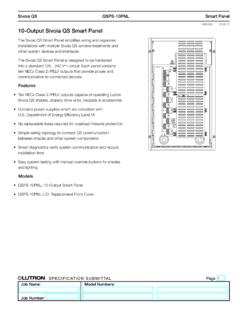
9 PD8-64-RU10-2L48 module 1 613 mm ( in) panel with 10 A RCBO breakers for United Kingdom and 230 V~, 3 phase 4-wire feedPD8-64-RU10-2L4 Shown with components. Components sold Support: +44.(0) Panels and HarnessesPDW-D-1 Wiring Harness for Dimming Power ModulePDW-S-1 Wiring Harness for Switching Power ModulePDW-T-1 Wiring Harness for 0-10 V Power ModulePDW-M-1 Wiring Harness for Motor Control Power ModulePDW-ED-1 Wiring Harness for EcoSystem or DALI Power ModulePDW-QS-4QS Link Wiring Harness for 4 Power Modules (PD4 Panels )PDW-QS-5QS Link Wiring Harness for 5 Power Modules (PD5 Panels )PDW-QS-8 QS Link Wiring Harness for 8 Power Modules (PD8 Panels )PDW-QS-9 QS Link Wiring Harness for 9 Power Modules (PD9 Panels )PDW-QS-10QS Link Wiring Harness for 10 Power Modules (PD10 Panels )Terminal Block KitsPDT-DS-1 Terminal Kit for Dimming or Switching Power ModulePDT-T-1 Terminal Kit for 0-10 V Power ModulePDT-M-1 Terminal Kit for Motor Control DIN Power ModulePDT-ED-1 Terminal Kit for EcoSystem or DALI Power ModuleDoorsPD-36-DOORR eversible Hinged Door for 921 mm ( in) DIN PanelsPD-64-DOORR eversible Hinged Door for 1 613 mm ( in) DIN PanelsBlanks/FillersPD-BLANK-1 DIN Panel Blanking Plate: 1 piecePD-BLANK-5 DIN Panel Blanking Plate: 5 piecesOptional AccessoriesTechnical Support: +44.
10 (0) Panels and Door Dimensions1 613 mm ( in) panel with optional mounting door. Door can be hung as swing-left or mm ( in)144 mm ( in)1 613 mm ( in)Technical Support: +44.(0) Panels and Door Dimensions921 mm ( in) panel with optional mounting door. Door can be hung as swing-left or mm ( in)144 mm ( in)931 mm ( in)Technical Support: +44.(0) Panels and Door ViewsOptional door available for 1 613 mm ( in) and 921 mm ( in) mm ( in) panel Door Models: PD-64-DOOR PD-36-DOORS wing-RightOptional panel door kit includes hinges and mounting hardware that can be configured to swing-left or right. Allow 508 mm (20 in) for swing clearance. Doors have a black, powder-coated finish. Kit can be installed after panel installation, but requires removal and reinstallation of the deadfront (flat cover). Standard door has a magnetic mm ( in)108 mm ( in)485 mm (19 in)485 mm (19 in)Technical Support: +44.