Transcription of Directional Control Valves - .:. Border Supply US
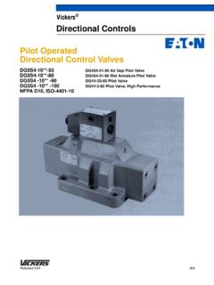
1 Vickers . Valves Directional Control Valves DG3*-H8; 30 and 10 Series, Pilot operated DG17*-H8; 30 and 10 Series, Manually operated DG5*-H8; 50 and 30 Series, Solenoid Controlled, Pilot operated ISO 4401 Size 08. Basic Characteristics Typical Section Mounting .. Surface mounting DG5*-H8-2C Spring-Centered Valve Example Max. pressure: DG*S .. 210 bar (3000 psi). DG*V .. 350 bar (5000 psi). Max. flow .. 700 L/min (185 USgpm). General Description which can be enhanced by optional DG**-H8 Valves are used primarily for stroke and/or pilot choke adjustments. Features and Benefits controlling the starting, stopping and Models include spring offset, spring High pressure and flow capability for direction of fluid flow. centered, pressure centered and maximum cost-effectiveness. detented versions. All are available with Low headloss to minimize power Basically, six series of Valves are the option of an integral P-port wastage.
2 Available grouped into DG*S moderate minimum-pilot-pressure generator. DG5* Low shock characteristics to pressure versions and DG*V high Valves can be arranged for internal or maximize machine life. pressure versions. There is a choice of external pilot pressure and/or drain Facility to change solenoid coils up to 18 different spools, dependent on connections. without disturbing the hydraulic valve configuration. These include envelope. meter-in and meter-out spools, and The many optional features, regeneration types that can obviate particularly for DG5* Valves , permit extra Valves essential in traditional matching to virtually every application circuit arrangements. All spools have within the valve's power capacity. been designed to provide good low shock, fast response characteristics March 1996 GB-2327A. Functional Symbols DG3*-H8 Pilot operated Models Comprehensive and simplified symbols.
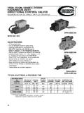
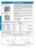
3 Spring Offset, End-to-End, Spring Offset, End-to-End, DG3-H8 Options DG3*-H8-*A Opposite Hand, DG3*-H8-*AL The following are shown in a Spool types: 0, 2, 6, 9, 52, Spool types: 0, 2, 6, 9, 52, DG3*-H8-*C example: 521, X2 , Y2 521, X2 , Y2 1. Pilot choke module 2. Minimum pilot pressure generator 3. Stroke adjusters at either or at both ends (shown at both ends in example). One or more options can be built into b a b a any DG3 series valve. X P T Y B A X P T Y B A. A B A B. X b a b a Y 1. Y X. P T P T. Spring Centered, DG3*-H8-*C Pressure Centered, DG3*-H8-*D. Spool types: All Spool types: All 3 3. b o a . 2. X P T Y B A. b o a b o a A B. X P T Y B A X L P T Y B A. b o a . A B A B. X Y X Y. b o a b o a . P T L P T X P T. DG5*-H8, Solenoid Controlled, Pilot operated Models Comprehensive and simplified symbols, shown configured for external pilot Supply and internal drain. Spring Offset, End-to-End, Spring Offset, End-to-End, DG5*-H8-*A Opposite Hand, DG5*-H8-*AL.
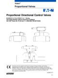
4 Spool types: 0, 2, 6, 9, 52, Spool types: 0, 2, 6, 9, 52, 521, X2 , Y2 521, X2 , Y2 . b o a b o a X P T Y B A X P T Y B A. A B A B a and b interchanged for spool types 4. and 8. b a b a X and Y spools require a stroke adjuster at one or both ends, dependent on the application, to limit stroke towards a . P T Y P T Y and/or b . 2. Spring Offset, End-to-Center Spring Offset, End-to-Center, Spring Centered, DG5*-H8-*C. Models Spool types Opposite Hand Spool types: All DG5*-H8-*B 0, 2, 521, X2 , Y2 Models Spool types DG5*-H8-*BL 4, 8 DG5*-H8-*B 4, 8. DG5*-H8-*BL 0, 2, 521, X2 , Y2 . b o a b o a b o a . X P Y B A X P T Y B A X P T Y B A. A B A B A B. b o o a b o a . P T Y P T Y P T Y. Pressure Centered, DG5*-H8-*D Detented, DG5*-H8-*N DG5*-H8 Options Spool types: All Spool types: 0, 2, 6, 9, 52, 521, The following are shown in a X2 , Y2 DG5*-H8-*C example: 1. Pilot choke module 2. Minimum pilot pressure generator 3.
5 Stroke adjusters, at either or at both ends (shown at both ends in example). 4. External pilot connection 5. Internal drain One or more options can be built into b o a b o a any DG5 series valve, the only exception being that the internal drain X L P T Y B A X P T Y B A option is not available with DG5*-H8-*D. A B A B (pressure centered) Valves . b o a b a L P T Y P T Y. 1. 3 3. b o a . 4 2 5. X P T Y B A. A B. b o a . a and b interchanged for spool types 4 and 8. X and Y spools require a stroke adjuster at one or both ends, dependent on the X P T. application, to limit stroke towards a and/or b . 3. DG17*-H8 Hand-Lever operated Models Spool Types Comprehensive and simplified symbols. Shown in 3-position form, plus 2. transients Spring Offset, End-to-End, Spring Offset, End-to-End, b o a DG17*-H8-*A Opposite Hand, DG17*-H8-*AL. Spool types: 0, 2, 6 Spool types: 0, 2, 6 0. 1. 2. b a b a 3. X P T Y B A X P T Y B A.
6 A B A B 6. b a Y b a Y. P T P T. 9. Spring Centered, DG17*-H8-*C Detented, DG17*-H8-*N. Spool types: 0, 2, 4, 6, 8, 33 Spool types: 0, 2, 4, 6, 8, 33. 11. 31. 33 &. b o a b o a 34 s X P T Y B A X P T Y B A 52. A B A B. b o a b o a 521. Y Y. P T P T. a and b interchanged for spool types 4 and 8. X2. Symbols on Nameplates Y2. Typical illustrations for: DG3*-H8-2D-1 DG5*-H8-3C-2-E-T-* X33. A B. 4 Y33. P T. 2 3 a o b 4. A B 1 A B. 1 8. P T T Notes: 1. In the detailed and simplified symbols on X L P T Y B A X P T Y B A this and the previous pages, the transient positions are omitted for simplicity. 1. On main stage 1. On main stage 2. In certain 2-position Valves , the o position 2. On cover plate 3. On pilot choke module becomes an additional transient, in 4. On pilot stage valve DG5*-H8-*A(L) and DG5*-H8-*N Valves . Notes: The performance of the 33 and 34 . a. For clarity pilot lines (dotted lines in illustrations) are omitted from the main-stage nameplate.
7 Spools differ only in the center position. b. Where a minimum pilot pressure generator (check valve symbol) is provided the letter P is Your Vickers representative can provide omitted from the nameplate for clarity. further details. 4. Application Notes Pilot Pressure Pilot Choke Adjustment Options a. Pilot pressure must always exceed These provide a meter-out flow Control tank line pressure by at least the system to the fluid in the pilot chambers requisite minimum pilot pressure. of main-stage Valves . This allows the This also applies when combining velocity of the main-stage spool to be open-center spools (0, 1, 4, 8, 9 and controlled, thereby reducing transient 11) with internal pilot pressure, but shock condition. For optimum results, a they should be used only with constant reduced pilot pressure is externally drained Valves . recommended. b. Internally drained Valves may be used Control Data, General only when surges in the tank line a.
8 Dependent on the application and the cannot possibly overcome the system filtration, any sliding spool minimum pilot pressure differential valve, if held shifted under pressure referred to above. When the for long periods of time, may stick and possibility of pressure surges in the not move readily due to fluid residue tank line exist, externally drained formation. It may therefore need to be Valves are recommended. cycled periodically to prevent this from happening. c. When DG5*-H8-*N Valves are de-energized the pilot and main b. Surges of fluid in a common drain line spools remain in the last selected serving two or more Valves can be of position, provided that pilot pressure sufficient magnitude to cause is maintained. If pilot pressure fails, or inadvertent shifting of the spools. falls below the minimum, the main It is recommended that circuit spool will spring center. protection be used, such as separate drain lines.
9 Caution: Because of this in-built feature the flow conditions of the center position must be c. Control by stroke adjusters, pilot selected with care, for the effect on both the chokes and minimum-pilot-pressure direction of flow and the pilot pressure. generator options is described far left. Minimum-Pilot-Pressure Generator Option Can be built into the P-port to create a specific minimum pilot pressure differential where internal pilot pressure is required with open-centered spools, 0, 1, 4, 8, 9 and 11. Stroke Adjustment Options These Control the maximum opening of the main spool/body passages by adjusting the limits of spool stroke. By this means, the response time and the pressure drop across the valve for any particular flow rate can be controlled. Stroke adjusters can be fitted at either or both ends of the main-stage valve for adjusting the stroke in one or both directions. One use of stroke adjusters is for controlling the metering characteristics of X* or Y* -type spools.
10 (See model code 5 .). 5. Model Code For pilot operated Valves : (F3-) DG3 * -H8- ** ** (-**) (-*) -**. 1 2 3 4 5 8 14. For hand-lever operated Valves : (F3-)DG17 * -H8- ** ** -**. 1 2 3 4 14. For solenoid controlled, pilot operated Valves : (F3-)DG5 * -H8- ** ** (-**) (-E)(-T) (-*) (-*) - (V) M - ** (L) -* 5 -**. 1 2 3 4 5 6 7 8 9 10 11 12 13 14. 1 Fluid compatibility 5 Spool Control 9 Manual override option Blank = Antiwear hydraulic oil 1 = Stroke adjustment at both ends Blank = Plain override in solenoid (class L-HM), invert emulsion 2 = Pilot choke adjustment both ends end(s) only . (class L-HFB), or water glycol 3 = 1 and 2 combined H = Water-resistant manual override (class L-HFC) 7 = Stroke adjustment, port A end on solenoid end(s) . F3 = As above or phosphate ester only Z = No override at either end (class L-HFD) 8 = Stroke adjustment, port B end No override in non-solenoid end of Note: For further information see Hydraulic only single-solenoid Valves .