Transcription of Vickers Directional Controls - Border Supply
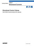
1 Speed control orifice plug, model code DG4V-5, 20 SeriesTypical Construction of a Spring-Centered DC Valve with Variable Speed Pilot control passageGeneral DescriptionMax. pressure315 bar (4500 psi).. Max. flow ratesUp to 120 L/min.. (32 USgpm),dependent on spoolMounting surfaceISO 4401 size 05.. NFPA D02 DIN 24340 (NG10)A range of four-port solenoid operateddirectional control valves with four-landspool design to facilitate provision ofsmooth, variable valve range includes:FAC and DC wet-armature solenoidoptions with ISO 4400 (DIN 43650)electrical connections and speed changeover potentialin all DC models; see ResponseTimes sectionFMany spool types; in spring-offset,spring-centered and Armature solenoid Operated DirectionalControl ValvesVickers Directional ControlsFunctional S ymbolsSol. BSol. AA BP TSol. BSol. AA BP TSol. BA BP TSol. AA BP TDouble solenoid Valves,Tw o-P ositi on, Detent edSingle S olenoid Va lves, solenoid at Port A EndSingle S olenoid Va lves, solenoid at Port B EndDouble solenoid Valves,Spring CenteredDG4V-5-*N valvesDG4V-5-*C valvesDG4V-5-*A valvesDG4V-5-*AL valvesDG4V-5-*BL valvesDG4V-5-*B valves2622222666310330000112222232377788 8113133345256521561521561565233343334313 11111 Tr ansient condition only.
2 Both ports TA and TB are CodePrefix, fluid compatibilityBlank = AC or DC-voltage models for petroleum oils, water-in-oil (invert) emulsions or phosphate models for water = DC-voltage models for water typeSee Functional Symbols sectionSpool spring arrangementA = Spring-offset, end-to-endAL = As A but left-hand buildB = Spring offset, end-to-centerBL = As B but left-hand buildC = Spring centeredN = Two-position, detentedSee also Functional Symbols sectionSpool designJ = All DC valves except 0A spool/spring arrangements. AC valves with 8B(L) and 8C spool/spring for 0A DC-valves and all ACvalves except 8B(L) and 8C spool/spring arrangementsManual override optionP = Standard overrides in both ends of single- solenoid valvesH = Water-resistant override(s) in solenoid end(s)BH2 = Water-resistant overrides in both ends of single- solenoid valvesZ = No overrides at either endOmit for standard plain override(s) insolenoid end(s) onlyBBNo override in non- solenoid end of single- solenoid energization identityV = solenoid A is at port A end and/or solenoid B is at port B end, independent of spool typeOmit for US ANSI standardrequiring solenoid A to connect P to Awhen energized and/or solenoid B toconnect P to BSpool position indicator switchS6 - LVDT type DC switch with Pg7connector plugElectrical connection(s)U = ISO 4400 (DIN 43650) mounting(s) without plug(s)
3 Coil ratingA = 110V AC 50C = 220V AC 50ED = 240V AC 50EK = 115V AC 60EH = 230V AC 60G = 12V DCH = 24V DCHL = 24V DC (32W)OJ = 48V DCP = 110V DCDesign number, 20 seriesSubject to change. Installationdimensions unaltered for designnumbers 20 to 29 inclusiveSpool speed controlJ06 = 0,6 mm orificeJ08 = 0,8 mm orificeJ10 = 1,0 mm orificeJ12 = 1,2 mm orificeJ99 = no orifice. Must be specifiedwhere future fitting of orifice is required,see page , Spool Speed ControlOrifice 56567878911108(F13-) DG4V-5-** *(L) (J) (-**)- (V) M- (S6)- U - ** 6- 20- J** Mounting Subplates and FixingBolt KitsSee catalogs 2425 and Electrical Plug(s)See end of Installation Dimensions DataMax. PressuresPorts P, A and B315 bar (4500 psi).. Ports TA and TB120 bar (1750 psi).. for AC bar (2325 psi)for DC DataFor coil ratings see in Model Code ConsumptionAC SolenoidsAC 50 HzAC 60 HzInrush, max.
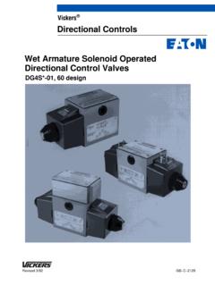
4 YVAS teady-state BVAH olding VA700375105750440130 All above values are RMSYA rmature fully retracted, 1st start of normal working stroke of valve spool. Previously called Inrush .DC SolenoidsAt rated voltage and wire temperature of20_C (68_F):Type HL32W.. Others38-42W.. Performance Data000246810121416 Pressure droppsibarFlow rate20406080100 120 L/min1002001505020510152530US gpm12345678910000 Pressure droppsibarFlow rate20406080100 120 L/min20510152530US Drops Typical with petroleum oil at 36 cSt (170 SUS) and a specific gravity of 0,87 Spool/spring codeSpool positionscoveredP to AP to BA to TB to TP to TA to B orB to A0A(L)Both2245 0B(L) & 0 CDe-energizedEnergized 1 1 6 73Y 1B(L) & 1 CDe-energizedEnergized 1 2 6 46B 2A(L)Both3356 2B(L) & 2 CAll2245 2 NBoth3356 3B(L) & 3 CDe-energizedEnergized 2 356 5 6B(L) & 6 CDe-energizedEnergized 3 35F66B7 6 NBoth4445 7B(L) & 7 CDe-energizedEnergized3F23B2 5 6 5g 8B(L) & 8 CAll22788 11B(L) & 11 CDe-energizedEnergized 2 1 4 76F 22A(L)Both33 23A(L)Both3356 31B(L) & 31 CDe-energizedEnergized 3 2 467 33B(L) & 33 CDe-energizedEnergized 2 212F512B6 34B(L)
5 & 34 CDe-energizedEnergized 2 211F511B6 52BL & 52 CAll7F84 9g56BL & 56 CDe-energizedEnergized 7F 88F610B 9g521B & 521 CAll87B 5 9g561B & 561 CDe-energizedEnergized 8 7B10F 8B7 9gYA and B blockedB A blockedF B blockedg P DataSpool Position Indicator ModelsSpool/spring arrangement types 0A (L), 2A(L), 22A(L)DC model type S6 This product has been designed and tested to meet specific standards outlined in the European Electromagnetic CompatibilityDirective (EMC) 89/336/EEC, amended by 91/263/EEC, 92/31/EEC and 93/68/EEC, article 5. For instructions on installationrequirements to achieve effective protection levels see this leaflet and the Installation Wiring Practices for Vickers ElectronicProducts leaflet 2468. Wiring practices relevant to this Directive are indicated byElectromagnetic Compatibility (EMC) .Input: Supply voltage10 to 35V DC inclusive of a maximum 4V pk-to-pk rippleCurrent, switch open5 mACurrent, switch closed255 mAOutput:Voltage1V below input at maximum loadMaximum continuous current250 mAMaximum load impedance136 at maximum input voltsMaximum switching frequency10 HzPlug connections:Pin 1 (output 1)Normally open (ie.)
6 Not connected to pin 3)Pin 2 Supply +vePin 30 VPin 4 (output 2)Normally closed (ie. connected to pin 3)Switching pointWithin the spool spring offset condition DConnectorPg7 plug (supplied with valve)ProtectionOverload and short-circuit protected; self 144 class IP65 with connector correctly Factory setting ensures this condition under all combinations of manufacturing tolerance and of temperature drift (see Temperature Limits ) .Customer s protective ground connectionSolenoidLVDTW arningAll power must be switched off beforeconnecting or disconnecting any ConnectionsElectricalPanelWARNING: Electromagnetic Compatibility (EMC)It is necessary to ensure that the unit is wired up in accordance with the connection arrangements shown above. Foreffective protection the user s electrical cabinet, the valve subplate or manifold and the cable screens should beconnected to efficient ground all cases both valve and cable should be kept as far away as possible from any sources of electromagneticradiation such as cables carrying heavy current, relays and certain kinds of portable radio transmitters, etc.
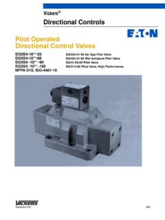
7 Difficultenvironments could mean that extra screening may be necessary to avoid the solenoid ValvesDC solenoid Valves000psibarFlow rate20406080100 120 L/min20510152530US gpm100200100020003000 Pressure30035040005000315450012345675&70 00psibarFlow rate20406080100 120 L/min20510152530US Flow RatesBased on warm solenoid (s) operating at10% below rated limits applicable to followingusages:1. All valves except those with types 22,52, 56, 521 and 561 spools havingsimultaneous equal flow rates from Pto A or B and from B or A to Valves with type 22 spools havingflow from P to A or B, the other beingblocked. T is drained at all Valves with types 52, 56, 521 and561 spools having one service portconnected to the full bore end of a2:1 area ratio double-acting cylinderand the other service port to theannulus Valves with type 23 spools havingsingle flow from A or B to T, P and theother service port being Vickers with application details ifany of the following are required:a) Single flow path, P to A, P to B,A to T or B to ) Substantially different simultaneousflow rates between P to A or B andB or A to ) Spools as in 3 above are to be usedwith cylinder ratios greater than about3:1 at low flow rates or 2.
8 1 at highflow codeAC valve graph curveDC valve graph curve0A(L)0B(L) & 0C1B(L) & 1C2A(L)2B(L), 2C & 2N3B(L), 3C, 6B(L) & 6C6N7B(L) & 7C8B(L) & 8C11B(L), 11C & 22A(L)23A(L)31B(L) & 31C33B(L), 33C, 34B(L) & 34C52B(L), 52C, 56BL, 56C,521B, 521C, 561B & Times, TypicalTime taken from when signal is firstapplied at the solenoid until the spoolcompletes its travel. Based onDG4V-5-2C at 60 L/min (16 USgpm)from P to A to B to T and at 160 bar(2320 psi) with petroleum oil at 36 cSt(168 SUS) and at 50_C (122_F):AC energizing30 ms.. AC de-energizing40 ms.. DC energizing120 msY.. DC de-energizing45 msY:.. :In pure switched conditions, devoid of the efffects of any suppression diodes and full-wave valves. Longer response times can be obtained by fitting an orifice plug in a special pilot port, standard in all bodies. An orifice kit 459065, containing a selection of plugs of differing orifice size, can be ordered separately.
9 Ask your Vickers representative for FluidsWater glycols can be used withF13-prefix DC-voltage models or withnon-prefix AC-voltage DC-voltage models and allAC-voltage models can be used withanti-wear hydraulic oils, water-in-oilemulsions, phosphate esters (not alkylbased).The extreme operating viscosity range isfrom 500 to 13 cSt (2300 to 70 SUS) butthe recommended running range is 54 to13 cSt (245 to 70 SUS).For further information about fluids seecatalog LimitsMinimum ambient 20_C ( 4_F).. Maximum ambient:AC 50 Hz valves50_C (122_F).. AC 60 Hz valves40_C (104_F).. DC valves70_C (158_F).. Fluid * 20_C( 4_F)+70_C(+158_F)+10_C(+50_F)+54_C(+130_ F)*To obtain optimum service life from both fluid and hydraulic system, 65_C (150_F) normally is the maximum temperature except for water-containing synthetic fluids consult manufactureror Vickers where limits are outside thosefor petroleum the actual temperature range,ensure that viscosities stay within thelimits specified in the Hydraulic Fluids Surface TemperaturesTypical maximums at 20_C (68_F)ambient:AC 50 Hz solenoids80_C (176_F).
10 AC 60 Hz solenoids92_C (197_F).. DC solenoids78_C (172_F).. Contamination control RequirementsRecommendations on contaminationcontrol methods and the selection ofproducts to control fluid condition areincluded in Vickers publication 9132 or561, Vickers Guide to SystemicContamination control . The book alsoincludes information on the Vickersconcept of ProActive Maintenance .The following recommendations arebased on ISO cleanliness levels at 2 mm, 5 mm and 15 mm. For products inthis catalog the recommended levelsare:Up to 210 bar (3050 psi)20/18/15.. Above 210 bar (3050 psi)19/17/14.. Mass, Approx. kg (lb)Single solenoid models,AC coils4,0 ( ).. Single solenoid models,DC coils4,8 ( ).. Double solenoid models,AC coils4,5 ( ).. Double solenoid models,DC coils6,3 ( ).. solenoid ModelsInstallation Dimensions in mm (inches)Y May vary according to plug The cable entry can be repositioned at 90_intervals from the position shown.