Transcription of Pressure Reducing Valves for Line Mounting - …
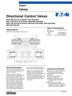
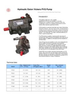
1 Typical SectionXTGageGageDrainXCTR emote controlGageGageDrainRemote controlPPPPR educedpressureReducedpressure(F3-) X (C) T- ** *2*123456123--UB7 Special sealsfor phosphate ester fluidsOmit if not requiredReverse free flow check valve, 06 and 10 sizes onlyOmit if not requiredNominal size03 = 3/8I06 = 3/4I10 = 11/4 IMaximum adjustable reducedpressure1 = 70 bar (1000 psi)2 = 140 bar (2000 psi)3 = 200 bar (2850 psi)Flow rate/min. reducedpressure combinationsFor use of, and performance data forsymbols B or F at this location, seetable Max. Flow Rate and Pressures on next number, 20 seriesSubject to change. Installationdimensions unaltered for designnumbers 20 to 29 threadsUB = G (BSPF) thread to ISO 228/14567-March 1996GB-2333 Pressure Reducing Valves for LineMountingXT-03, 20 SeriesX(C)T-06/10, 20 SeriesBasic CharacteristicsMaximum supply pressure210 bar.
2 (3000 psi)Maximum flow284 l/min.. (75 USgpm)General DescriptionPressure Reducing Valves are used toreduce system Pressure to a constantreduced outlet Pressure regardless offluctuations in the main system above theselected XCT models have an integral checkvalve that allows free flow from the outletconnection to inlet SymbolsModel CodeVickers Pressure ReliefOperating DataTemperature LimitsAmbient:Minimum 20_C ( 4_F).. Maximum+70_C ( +158_F).. Fluid TemperaturePetroleumWater-oilcontainingM in. 20_C+10_C( 4_F)(+50_F)Max.*+80_C+54_C(+176_F)(+130_ F)*To obtain optimum service life from both fluid and hydraulic system, 65_C (150_F) is the recommended maximum fluid temperature, except for water-containing synthetic fluids consult the fluidmanufacturer or Vickers where limitsare outside those for petroleum ControlRequirementsRecommendations on contaminationcontrol methods and the selection ofproducts to control fluid condition areincluded in Vickers publication 9132 or561, Vickers Guide to SystemicContamination Control.
3 The book alsoincludes information on the Vickersconcept of ProActive Maintenance .The following recommendations arebased on ISO cleanliness levels at 2 mm, 5 mm and 15 mm. For products inthis catalog the recommended levelsare:Up to 210 bar (3000 psi)19/17/14.. Mounting PressureInlet ports210 bar (3000 psi).. Drain ports1,7 bar (25 psi).. Note: Drain ports must be piped direct toreservoir. Any back Pressure at this port willincrease the effective Pressure setting of thevalve by the same Flow Rate and Min. Reduced PressuresTypical with petroleum oil at 21 cSt (102 SUS) and at 50_C (122_F).Model typeReduced Pressure rangeMax. flow rateMaximumbar(psi)Minimumbar(psi)L/min (USgpm) XT-03-1B-1F70(1000)5,2510,4(76)(150)2653 ( )(14)-2B-2F140(2000)5,2510,4(76)(150)265 3( )(14)-3BY-3F200(2850)10,4(150)53(14)X(C) T-06-1B-1F70(1000)5,613,8(81)(200)57114( 15)(30)-2B-2F140(2000)5,613,8(81)(200)57 114(15)(30)-3B-3F200(2850)5,613,8(81)(20 0)57114(15)(30)X(C)T-10-1B-1BJ-1F70(1000 )6,911,415,5(100)(165)(225)95190284(25)( 50)(75)-2B-2BJ-2F140(2000)6,911,415,5(10 0)(165)(225)95190284(25)(50)(75)-3B-3BJ- 3F200(2850)6,911,415,5(100)(165)(225)951 90284(25)(50)(75)YXT-03-3B combination not recommended.
4 If max. inlet Pressure is required with min. rated reduced Pressure , consult your Vickers data giving max. flow for -*B- Pressure SettingFor proper functioning the inlet pressuremust be maintained at least 10 bar (150 psi) above the setting of the reducedoutlet Pressure ControlReduced Pressure may be adjustedremotely by connecting the remote controlconnection to the inlet port of a C-175relief valve (catalog 411) or a CGR-02relief valve (catalog 409). Pressure setting of the X(C)T valve mustbe higher than that of the remote FluidsX(C)T Valves are suitable for use withhydraulic oils, oil-in-water emulsions andwater fitted with special seals (specify F3 in model code ) these Valves aresuitable for use with phosphate esters(not alkyl-based).The extreme operating range is from 500to 13 cSt (2270 to 70 SUS) but therecommended running range is 54 to 13 cSt (245 to 70 SUS).
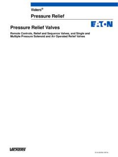
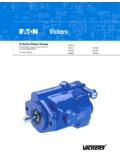
5 Performance DataPilot Control (Drain) FlowPressure Drop2001501005000100020003000psibarReduc ed pressureFlow rateL/min02001501005000100020003000psiba rReduced pressureFlow rateL/min02001501005000100020003000psiba rReduced pressureFlow rateL/min010 20 30 40 50 6010515-3F-2F-1F-2B-1 BXT-03-**X(C)T-06-**-3F-2F-1F-2B-1B20 40 60 80 100 120102030-3F-2F-1F-2B-1B50 100 150 200 250 30020406080X(C)T-10-**000501001257525501 001502001000200030000,511,52barpsiL/minP ressure dropDrain flow ratein3 /minXCT-06 XCT-10000100 200 300 400500 600 L/min255075100 125 150 USgpm51015bar50100150200psiPressure dropFlow rateUSgpmUSgpmUSgpmTypical range3 Typical with petroleum oil at 21 cSt (102 SUS) and at 50_C (122_F).Reduced Pressure OverrideInstallation Dimensions in mm (inches)High Pressure inlet, (or reversefree flow outlet for XCT models).
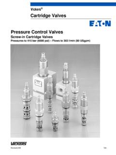
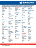
6 K thread .3rd angleprojectionReduced pressuregage connection, G1/4 Pressure adjustment clockwise to increase Pressure ,counter-clockwise to decrease locknut is re-tightened for XCT modelsAGCDEFJBHigh Pressure gageconnection, G1/4 Remote controlconnection, G3/8 Remote controlconnection, G1/4 Adjustable reduced pressureoutlet, (or reverse reversefree flow inlet for XCTmodels). K ,5( )max. 47,8( dia)14 ( ) A/F to 15-25 Nm(20-34 lbf ft)Drain G1/4 Cover fixing screws:03 size:5/16I-18 UNC soc. hd. cap screwTorque to 27-33 Nm (37-45 lbf ft)06 size:3/8I-16 UNC soc. hd. cap screwTorque to 48-58 Nm (65-77 lbf ft)10 size:3/8I-16 UNC soc. hd. cap screwTorque to 48-58 Nm (65-77 lbf ft)Optional positions of adjustmentcontrol obtained by rotating coverassemblyFFFNot for XT-10FH44CS-03 and 4CT(1)-06/10, Pipe-Mounted ModelsModelABCDEFGHJKXT-03142,2( )116,8( )69,1( )46( )39,6( )69,4( ) 69,9( )35,1( )G3/8IX(C)T-06176,5(7)151,1( )96,8( )69,9( )39,6( )87,2( )106,4( )92,2( )50,8(2)G3/4IX(C)T-10211,2( )182,6( )109,7( )81( )68,3( )117,3( )147,6( )117,3( )86,4( )G11/4 IMassXT-033,2 kg (7 lb).
7 XT-065,6 kg ( lb).. XT-1012,1 kg ( lb).. XCT-065,9 kg (13 lb).. XCT-1013,0 kg ( lb).. Ordering ProcedureSpecify full Model Code.