Transcription of Vickers Directional Controls Wet Armature …
1 Revised 3/92GB C 2129 Vickers Directional ControlsDirectional control ValvesWet Armature solenoid OperatedDG4S*-01, 60 design2 Table of ContentsBasic Characteristicts3.. Functional Symbols3.. Model Code4.. Maximum Pressure4.. Solenoids4.. Pressure Drop5.. Maximum Flow6.. Installation Dimensions7.. DG4S2 012A * 60DG4S4 01*A * 60DG4S4 01*B * 60DG4S4 01*F * 60DG4S4 01*C * 60DG4S4 01*N * 60DG4S2 01*N * 60 Installation Dimensions8.. SDG4S4 01*A * 60 Installation Dimensions9.. PBDG4S* 01** * 60 Installation Dimensions10.. PA*DG4S* 01** * 60PA5DG4S* 01** * 60 SPA5DG4S* 01** * 60 Installation Dimensions11.
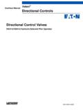
2 W, WT & WL ModelsInstallation Dimensions12 .. U ModelsMounting Subplates and Bolt Kits13.. 3 Basic characteristicsMax. pressure Up to 250 bar (3600 psi) dependent on fluidMax. flow rates Up to 95 l/min (25 USgpm) dependent on spoolMounting ISO 4401-05/patternCETOP 5/NFPA-D05 General descriptionDG4S* models are direct solenoidoperated, 2-way or 4-way directionalcontrol valves. Their primary function in ahydraulic circuit is to direct fluid flow to awork cylinder or to control the directionof rotation of a hydraulic connections are made by mountingthe valve on a manifold or subplatecontaining the are available with AC or DCwet- Armature solenoid (s).
3 Electricalconnections to the valve are made in anelectrical wiring housing or by variousplug-in devices. A ground terminal symbolsStandardSpoolTypesGraphicSymbolCe nterCondition A" ModelsSpring Offset B" ModelsSpring Centered C" ModelsSpring Centered F" ModelsSpring Offset N" ModelsDetented(No Spring)01112331678332(2-way)Standard (right hand) build shown. A" solenoid BP TA BP TbbbbbA BP TbbbbbbbbbbA BA BA BP TP TP TbaA BP TA BP TA BP TbabababababababababbbbbbA BP TbbbbA BbA BbA BP TP T Note On all models, when solenoid a" isenergized, flow is always P" to A".
4 Whensolenoid b" is energized, flow is always P"to "B". This is in accordance with standard. Solenoiddesignations a" and b" are identified onthe diagram plate on the side of the A BA BA BA BP TP TP TP TA BP TA BP TA BP TA BP TA BP TA BP TA BP TA BP TA BP TA BP TA BP TA BP TA BP TA BP TA BP TA BP TA BP TA BP TA BP TA BP T 4 Model Code12345678910111 SealsBlank - Standard sealsF3 - Special seals2 Monitor switchS - Monitor switch (Available as A" spring offset model only)Omit if not plug optionsPA - Insta-plug (male only)PB - Insta-plug male &female receptaclesPA3 - 3 pin connectorPA5 - 5 pin connectorOmit if not direction2 - 2 way4 - 4 way5 Electrical accessoriesL - solenoid indicator lightsW - Wiring housingLW - Wiring housing with indicator lightsWT - Wiring housing with terminal stripOmit if not typesSee Functional symbols" arrangementA - Spring offset, P to AB - Spring centered, solenoid a"removedC - Spring centered, three positionF - Spring offset, P to A.
5 Shift to centerN - No spring, detented8 Wet Armature solenoid (s)(Non-serviceable core tubes)Blank - Flying lead coil(s)U - DIN 43650 coil(s) without electrical plug9 Coil identification letter(s)See Solenoids" numberSubject to change. Installation dimensions remain as shownfor designs 60 through hand assemblyOmit for right hand assembly withsolenoid a" DIN 46350 electrical plug(s)See U models" in Installationdimensions" mounting subplates and bolt kitsSee Installation dimensions" and Ordering procedure" pressurePorts P, A & B 250 bar (3600 psi)*Port T70 bar (1000 psi)*70 bar (1000 psi) with high water basefluids (95% maximum water content) SolenoidsSolenoid IdentificationLetterSolenoid Voltage RatingInrushAmps(rms)HoldingAmps(rms)
6 HoldingWatts120 VAC 60 Hz110 VAC 50 Hz240 VAC 60 Hz220 VAC 50 Hz240 VAC 50 Hz110 VAC 50 Hz220 VAC 50 Hz12 VDC 24 VDC48 VDC250 VDC125 energizingSpring centered and spring offset valveswill be spring positioned unless thesolenoid is energized detented valves may beenergized momentarily, second; when the solenoid isde-energized the spool will remain inthe last position attained, provided thereis no shock, vibration or unusualpressure transients. NOTEAny sliding spool valve, if held shiftedunder pressure for long periods, maystick and not spring return, due tosilting.
7 Therefore, it is recommendedthat the valve be cycled periodically toprevent this from following response times weremeasured from the point of energization/de-energization to the point of firstindication of inlet pressure timeModelValve typeAC SolenoidDC SolenoidShiftReturnShiftReturn50 ms50 ms30 ms60 ms80 ms60 ms80 ms40 ms25 ms18 ms20 ms18 ms18 ms25 msSpring centeredSpring offsetSpring offsetDetentedB/CAFNR esponse up to full system pressure isdependent on the system's compressedvolume and can vary with eachapplication.(F3) - * ** DG4S * ** - 01 ** * - (U) - ** - 60 - (LH)5 DrainOn 2-way valves, T" is the drain andmust be connected to the tank through asurge-free line, so there will be no backpressure at this port.
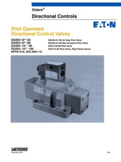
8 NOTES urges of oil in a common line servingthese and other valves can be ofsufficient magnitude to cause inadvertentshifting of these valves. This isparticularly critical in the no-springdetented type valves. Separate tanklines, or a vented manifold with acontinuous downward path to tank, dropsThe pressure drop curves giveapproximate pressure drop (DP) whenpassing 21 cSt (100 SUS) fluid ( specific gravity) through theindicated flow any other viscosity, the pressure drop(DP) will change as follows:For any other specific gravity (G1), the pressure drop (DP1) will beapproximately.
9 DP1 = DP (G1/G)Viscosity cSt(SUS)14(75)32(150)43(200)54(250)65(30 0)76(350)86(400)% of DP (Approx)93111119126132137141 Pressure drop curve reference chartSpool typeCurve numbersP-A B-T P-B A-T P-T0C/N1C11C2C/N3C31C6C/N7C/N8C33C/N2 way2A2A-LH2N2122334133121221124233233341 3311221212422-------6-272---722---Pressu re drop curve reference chartSpool typeCurve numbersP-A B-T P-B A-T0A/F0A/F-LH1F1F-LH2A/F2A/F-LH3F3F-LH6 A/F6A/F-LH7A/F7A/F-LH121-242-2412222-241 -122322-253-2632222-242-23242 PRESSURE DROP - psidPRESSURE DROP - bar020 406080 100026101418222620181614121086420 FLOW - USgpmFLOW - l/min12345670204060801001201401601802002 202402602806AC & DC solenoid valvesAC & DC
10 solenoid valvesFLOW - USgpm02 61014 182226020 40 60 80 100 FLOW - l/min05010015020025030010002000300040000 FLOW - USgpm02 6 101418 2226020 40 60 80 100 FLOW - l/min300200250150100500123456 Maximum flow dataMaximum recommended flow data is forAC or DC solenoids at 90% nominalvoltage in a 4-way circuit with cylinderports either looped or blocked andcontaining 2,5 liter (.66 USgpm)compressed volume. Reducedperformance may result when certainspools are used in 3-way F3 seals are required for usewith phosphate ester type fluids or theirblends. Standard seals are suitable foruse with water glycol, water-in-oilemulsion fluids, HWBF (95% maximumwater content), and petroleum 4406 Code 18/15 Operating to 50_C (70_ to 120_F)Fluid - 51 cSt (75-250 SUS)