Transcription of Temposonics m - Vickers Hydraulics
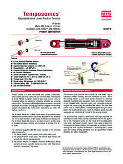
1 Temposonics MagnetostrictivePosition SensorsE-SeriesAnalog + Start / StopTemposonics EPMeasuring range 50 - 1500 mm / 50 - 3250 mmmSENSORSM agnetostrictionThe absolute Temposonics linearposition sensors are based on theMTS developed magnetostrictivemeasurement principle. That combi-nes various magneto-mechanicaleffects and uses the physical heightprecise speed-measurement of anultrasonic wave (torsion pulse in itssensor element) for position detec-ting. sensor integrated signal proces-sing transforms the measurementsdirectly into market standard contactless principle - an exter-nal movable magnet marks the posi-tion - eliminates the wear, noise anderroneous signal problems and gua-rantees the best durability withoutany factorTemposonics are extremely robustsensors, ideal for continuous opera-tion under harshest industrial condi-tions.
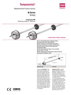
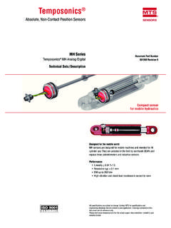
2 The sensor is completelymodular in mechanics and electro-nics A profile sensor housingprotectsthe sensor element in which givesrise to the measurement The sensor head, a solid diecastaluminum housing, accommodatesthe complete modular electronicinterface with active signal conditio-ning. Double encapsulation ensureshigh operating safety and optimumEMC The external position transmitter isa permanent magnet. It is fitted at themobile machine part, taken over thesensing Linear, Absolute Measurment Contactless Sensing with Highest Durability Rugged Industrial sensor , EMC shielded and CE certified High-Precision: Linearity better 0,02 % Repeatability 0,001 % Direct Position Outputs: - Analog (V/mA)- Start / Stop + sensor -Parameter Upload Measuring Range 50 - 1500 mm / 50 bis 3250 innovative sensor -Parameter HandlingI2 ITemposonics-EPAnalog + Start / StopMTS Sensors Temposonics -EP A stable profile versionMeasuring range:50 - 1500 mm50 - 3250 mm (Start / Stop output R3)A robust aluminum profile offers modular construction, flexible mounting confi-gurations, and easy installation.
3 Position measurement is contactless via twoversions of permanent magnets. A captive sliding magnet running in profile housing rails. Connection with themobile machine part is via a ball jointed arm to taking up axial forces. A floating magnet, mounted directly on the moving machine part, travels overthe profile at a low distance. Its permissible misalignment allows a not comple-tely parallel DataInputMeasured variableDisplacementMeasuring range50 - 1000 mm / 50 - 3250 mm for start/stop output R3 Output1. Voltage0 - 10 VDC or 10-0 VDC (Controller input resitance RL: > 5 kOhm)2. Current4 - 20 mA or 20-4 mA, ( load: Ohm)3. Start/StopRS-422 differential signal, additional available: Serialparamter upload of Measuring range, Offset, Gradient (Ultrasonic speed of sensing pulse), status and manufacturer numberAccuracyResolutionAnalog: InfiniteStart/Stop: 0,1 / 0,01 / 0,005 mmLinearity, uncorrect< 0,02 % (Minimum 60 m)Repeatability< 0,001 % frequencyAnalog: > 1,5 kHz / Digital: controller dependentRipple< 0,01 % / Digital: controller dependentOperating ConditionMounting positionAnyMagnet speedAnyOperating temeprature40 C.
4 +75 CDew point, humidity90 % rel. humidity, no condensationIngress protectionIP 65 if mating cable connector is correctly fittedShock rating100 g (Single hit) / IEC-Standard 68-2-27 Vibration test10 g / 10 - 2000 Hz / IEC-Standard 68-2-6 EMC TestElectromagnetic emmision EN 50081-1 Electromagnetic immunity EN 50082-2EN 61000-4-2/3/4/6, Criteria A / CE qualifiedForm factor / MaterialSensor headAluminumSensor housingAluminumPosition magnet typeMagnet sliderInstallationMounting typeAdjustable mouting clampsElectrical connectionConnection type6 pin connector M16 Input voltage24 VDC (+20 % / -15 %)Current consumption50 - 140 mA (Digital 50 - 100 mA), stroke length dependentRipple< 1 % s-sElectric strength500 V (0 V ground to machine ground)
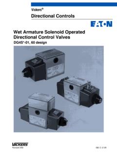
5 Polarity protectionUp to -30 VDCO vervoltage protectionUpt to 36 VDCI3 ITemposonics-EPAnalog + Start / StopMTS Sensors forward actingreserve actingPosition magnetSensor elementU/I0sActive sensor strokeMeasuring rangeAnalog outputTemposonics-EP are provided with an integrated analog interface and can beconnected to a control system or indicator directly without an interface. themicrolectronics in the sensor head generates continuous, strictly displacementproportional voltage and current outputts whose upscale or downscale outputaction can be selected when ordering. The output variables are is not outputDigital Temposonics -EP is equipped with a start/stop output. The sensor requi-res a start signal from an external indicator in the control system and returns asignal corresponding to the magnet position.
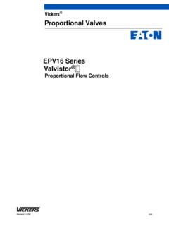
6 The time elepsed between the twosignals is proportional to the magnet position, to the displasement. Timemeasurement is by the indicator and used for calculating the position easy adaption to user s control systems, following sensor Measuring range - Offset- Gradient- Status- Manufacturer numbercan be read into controller without additional wiring. It can be done simply byusing the standard signal 0-10 V 10-0 V 4-20 mA 20-4 mA+_+_StartStop124 SensorTime intervalPositionStart/Stop InterfaceInterface modul3 Active sensor strokeStart/Stop + Parameters Upload Measuring range Offset Gradient Status Manufacturer numbermm+ 0,3+ 0,2- 0,1+ 0,10,0- 0,2- 0,301002003004005006007008009001000mmLin earity protocolSensor Temposonics -EP, measuring range 1000 mmTolerance allowed: 0,2 mmTolerance measured: typical 0,09 mm, uncorrectedI4 ITemposonics-EPAnalog + Start / StopMTS Sensors ProfileThe sensor is fixed on a straight surface of the machine with the movablemounting clamps.
7 These are provided in stroke length dependent number andare evenly on the profile to be distributed. We recommendend screws M5 x 20(DIN 6912) for attachment with a torque of max. 5 Nmto be !The EP sensor is now fixed isolated from machine ground. It is necessary thatsensor housing is grounded with flat pin terminal on the sensor head (1).Position transmitterU-Magnet: For accurate position measurments mount the magnet (1)with non-mangetizable fastening material (2)(screws, supports etc.).Using magnetizable supports, note that the magnet must be mounted with non-ferrous (3)of 5 mm minimum and magnet: The magnet (4)can be fixed with standard material and screws(5)Note the clearance, as shown right.(1)(2)M4(3)Maximum gap:3 mm ( 1mm)Maximum gap:3 mm ( 2 mm)(4)(1)11M4(5)Sliding mounting clampTightening torque for M5 x 20machine screws: max.
8 5 NmAttention!do not exceed the allowed maximum gapConnector D60 Cable*Analog (V)Analog (mA)Start/StopPin V4-20 mA*Stop (-)Pin 2pinkDC GroundDC GroundStop (+)Pin V20 - 4 mA*Start (+)Pin 4greenDC GroundDC GroundStart (-)Pin 5brown+24 VDC (-15/+20%)Pin 6whiteDC Ground (0V)* Accessory: Cable assembly with- Cable connector, female (page 6)- Cable K27 (LiYCMY 3 x 2 x 0,14 mm2)Cable shield is soldered on connector housing and must be grounded in the control unit.*Only ordered current output is face of sensor plugor rear of cable connector154326I5 ITemposonics-EPAnalog + Start / StopMTS Sensors Measuring range 50 - 1500 bzw. 50 - 3250 mmca. 39ca. 54 sensor stroke198 MountingzoneActive stroke Length396840 SensorheadMounting clamp14,546inactiv57 Magnet slider S Null-PositionBall jointed arm M5, vertical 18 / horizontal 360 1948ca.
9 58 Ball jointed arm M5, 18 RotationMagnet slider V 263,55735,5506854,548,5509,5M5 Hole- 5,5 Null-PositionTemposnics-EPAll measurments in mmConnector outlet D606 pol. Ger testecker M16M4354120,7 Maximum gap3 mm ( 1 mm)Non-magnetizablesupport, screws32,5M4 Mounting supportMaximum gap3 mm ( 2mm)6203119,5 4,3 MagnetU-Magnet M Block magnet L Null-PositionNull-PositionI6 ITemposonics-EPAnalog + Start / StopMTS Sensors Position gap 3 mm ( 1)Magnet slider SPart No. 252 182 Part No. 252 184 Magnet slider VU-Magnet M OD33 Part No. 251 416-220244314M540 Rotation:Vertical 18 Horizontal 360 331457 Rotation 18 60 : 8 mm 4,2 oncircle 2424M5 GFK, Magnet HartferritWeight ca. 30 goperating temeprature: -40.
10 +75 CGFK, Magnet HartferritWeight ca. 30 gOperating temperature: -40 .. +75 CPA-Ferrit-GF20 Weight ca. 11gOperating temperature: -40 .. +100 C 19,5 Housing: Zinc, nickel platedTermination: SolderContact insert: Silver platedCable clamp PG7/M16:Max. cable- 6 mmMax. cable- 8 mm3854 18546 pin female connectorM16, PG7 Part No. ST C0 9131 D6 pin 90 female connector M16insert adjustable 45 positionsPart No. ST C0 9131-6 Other magnets upon requestAlle Ma angaben in mmBlock magnet LPart No. 252 887 Bracket: CuSN6 zinc coatedMagnet: HartferritWeight: ca. 20gOperating temperature: +75 CCable connector(recommended, not on delivery)I7 ITemposonics-EPAnalog + Start / StopMTS Sensors TemposonicsSensor ModelS - Magnet slider, joint at topV - Magnet slider, joint at frontM - U-Magnet OD33L - Block magnet LMeasuring range0050 - 1500mm0050 - 3250mm (Output R3, see below)