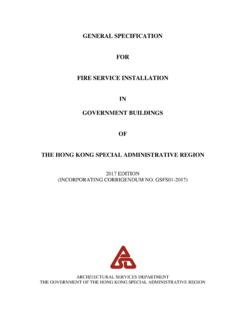
Transcription of DOUBLE INTERLOCK, PREACTION SYSTEM
1 JUNE, 2019HD 128 PAGE 1 OF 6HD FIRE PROTECTPVT. LTD. DOUBLE interlock , PREACTION SYSTEM WITH ELECTRIC/PNEUMATIC RELEASESIZE 50, 80, 100, 150 & 200 NBDELUGE VALVE Model H3, UL ListedCHECK VALVE Model-CH SPRINKLER ALARM UL Listed (Optional)RELEASE PANEL UL Listed (Optional)WATER FLOW UL Listed SWITCHSOLENOID VALVE 24V DC, UL ListedAUTOMATIC AIR Oil-less Risermount SUPERVISOR Compressor (Optional)AIR PRESSURE PMD-1 (Optional) MAINTENANCE DEVICE MANUAL SYSTEM UL Listed, Butterfly Valve - SHUTOFF VALVE Standard supply. (Gate Valve - Optional)MAXIMUM WORKING (250 PSI)PRESSURESYSTEM END Grooved (Standard supply) CONNECTION Flanged (Optional supply)APPROVAL UL ListedTECHNICAL DATADESCRIPTIONThe DOUBLE interlock PREACTION SYSTEM with Electric/Pneumatic Release is generally used to protect water sensitive areas such as computer rooms, storage areas, refrigerated areas etc.
2 , to avoid water damage due to inadvertent flooding of the sprinkler SYSTEM piping. In normal condition, PREACTION SYSTEM does not contain water in the sprinkler piping. The sprinkler piping contains air pressure for the purpose of supervising its leak tightness. This is most commonly used SYSTEM . This SYSTEM utilizes a deluge Valve H3 and Riser Check Valve Model CH. The Riser Check Valve isolates the deluge Valve from the SYSTEM air pressure. Riser Check Valve provides an air check so that the SYSTEM can be automatically pressurized with a supervisory air or nitrogen pressure of 42 PSI ( Bar). A supervisory low pressure alarm switch can be set at 20 PSI ( Bar), on decreasing pressure, to indicate whether there are any abnormal leaks in the sprinkler SYSTEM piping.
3 Loss of air pressure from the SYSTEM due to accidental leakage will not cause deluge Valve to releasing trim for deluge Valve utilizes a Solenoid Valve and a Dry Pilot Actuator in a series configu-ration. The SYSTEM air pressure holds the Dry Pilot Actuator closed, whereas the Solenoid Valve remains closed until it is electrically energized by a deluge Valve Releasing Panel (automatic control unit). The Releasing Panel is operated either by a fire detection device or manual electric pull station. In order for the DOUBLE interlock Pre- action SYSTEM to automatical-ly actuate, two independent events must occur. The deluge Valve Releasing Panel must operate and open the Solenoid Valve upon automatic operation of the electric fire detection initiating circuit and the sprin-kler SYSTEM piping must lose air pressure due to op-eration of one or more sprinklers.
4 The DOUBLE Inter-lock Pre- action SYSTEM will automatically actuate only when both the Dry Pilot Actuator and the Solenoid Valve are open at the same time. Unintended opening of just the Dry Pilot Actuator or the Solenoid Valve will only cause an alarm and not actuate the SYSTEM or flood the sprinkler SYSTEM Valve H3 is diaphragm valve as described in Technical Data Sheet HD & COMMISSIONINGThe PREACTION SYSTEM valves, panel, indicators must be installed in a readily visible and accessible location. The SYSTEM valves and accessory shall not be installed in an area having temperature less than 4oC (40oF).
5 Heat tracing to SYSTEM valve and accessory is not permissible. The SYSTEM must be installed and operated carefully by a trained person, having good knowledge of equipment. All SYSTEM piping must be flushed thoroughly before commissioning. After initial successful tests, an authorized person must be trained to perform inspection, testing and maintenance of the SYSTEM . JUNE, 2019HD 128 PAGE 2 OF 6HD FIRE PROTECTPVT. SEQUENCE OF INSTALLATIONSIn planning the installation, consideration must also be given to the disposal of relatively large quantities of water that may be associated with draining of the SYSTEM or performing flow Install the deluge Valve on Riser in vertical Install the Riser Check Valve above deluge Valve as shown in installation On completion of SYSTEM piping, install all the trims as per the trim drawing.
6 Care must be taken to ensure that Check Valves, Strainers, Valves etc. are installed with the flow arrows in the proper Connect all drain piping as shown in the All unused opening on valve or trim parts must be Connect air supply Connect all electrical to control panel as per wiring Make sure that all the nut bolts, fittings are screwed Follow the valve resetting and test The pipe fittings and nipple must be cleaned. Use thread sealent on male threads For common drain piping a check valve to be provided interconnecting main dran and the The drain tubing to be drip funnel must be installed with smooth bends that will restrict The drain piping must be free-flow and care must be taken to direct the drain in proper area to avoid damage due to release of A supervisory air or nitrogen supply is to be installed as given in the data sheet.
7 An air dryer, if specified, needs tobe installed as per authority having The electric connection through conduit is to be made as per authority having PROCEDUREa. Close the upstream side stop valve of the deluge Open drain valves and allow water to drain (if water flow was establish) & close drain valve when water flow has Check all release devices are closed. Inspect the release devices if SYSTEM was subject to fire Open the air supply line and check the pressure is maintained up to 42 PSI ( Bar). and Control Panel is kept Open the priming line so that the diaphragm chamber reads the SYSTEM water pressure.
8 Open the manual release station partly to vent the air & then close Open the upstream side of stop valve to read the deluge Valve Inlet water supply pressure. The deluge Valve is Check all the trim parts for possible AND MAINTENANCEI nspection and testing is to be carried out only by an authorized and trained personnel. DO NOT TURN OFF the water supply or close any valve to make repair(s) or test the valve, without placing a roving fire patrol in the area covered by the SYSTEM . Also inform the local security personal and central alarm station, so that there is no false alarm signal.
9 It is recommended to carry out physical inspection of the SYSTEM at least twice a week. The inspection should verify that no damage has taken place to any components and check for following normal condition of the SYSTEM . The owner is responsbile for maintaining the pre- action CONDITIONa. All main valves are open and sealed with tamper proof All drain valves are in closed No leak or drip is detected from drip All water gauge of deluge valve, should show the required No leak in any trim or other Release panel is on and no abnormal indication are All testing procedure to be Procedure outlined below will result in operation of associated alarm.
10 Concerned authorities to be in-formed about the tests before conducting the , 2019HD 128 PAGE 3 OF 6HD FIRE PROTECTPVT. TEST WATER FLOW ALARM TESTOpen the sprinkler alarm gong test valve, the water will flow through sprinkler alarm and/or water flow switch. On satisafctory observation close the alarm test valve. SOLENOID VALVE TESTa. Close the inlet valve of deluge Valve and open the main drain Close the air supply valve and drain the air pressure by opening drain valve of check Activate the solenoid valve through detector (zone-1) or manual release Observe water flow through solenoid valve Deactivate solenoid valve deactivating the initiating zone (zone-1/ zone-2).