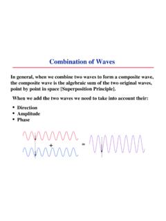
Transcription of Double slit interference and single slit diffraction ...
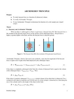
1 Brooklyn College 1 Double slit interference and single slit diffraction Purpose 1. Study Double slit interference of light waves 2. Study single slit diffraction of light Introduction When a monochromatic and coherent light passes through a single or Double slit, it creates a diffraction / interference pattern on a screen placed beyond the slits. The pattern formed is because of the superposition of the waves coming from the slit (or two slits). Double slit interference Figure 1 shows a configuration for Double slit interference experiment. Monochromatic and coherent light such as laser is incident on two narrow slits, S1 and S2. These two slits act as two coherent sources of spherical waves of the same wavelength. These waves interfere to form interference pattern on a distant screen. interference pattern due to a Double slit will have dark and bright fringes due to destructive and constructive interference of the waves coming from the two slits. Let l is the wavelength of the light, d is the slit separation, W is the width of the slits, L is distance from the slits to the screen, O is the center point on the screen opposite to the slits.
2 Any point on the screen P can be characterized by distance y from the mid-point O. Depending upon position of point P, we can observe bright fringe if the path difference between the two waves, Dl = ml, where m = 0, 1, 2,.. that satisfies constructive interference . The point P will be dark fringe the path difference Dl = (m - ) l, where m = +1, +2, .. for dark fringes above the center point O, and Dl = (m + ) l, where m = - 1, - 2, .. for dark fringes below O. Will point O be dark or bright? Why? Check the following simulator to give you better understanding: Figure 1: interference of circular waves from the two slits o S1 S2 P Incident light Screen d q q Dl y Brooklyn College 2 Alternatively, a position on the screen can be characterized by an angle formed by the line from the slits to this position, relative to the perpendicular line. Then y = L tan . For constructive interference criterion Dl = d sin = m , For L >> d, the angle is small and we can approximate sin tan = y/L.
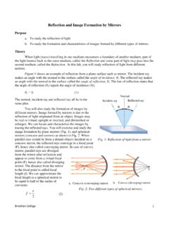
3 Substituting y/L for sin in the above equation, we get "#= l, or, rearranging, ='l#( (1) Distance between two successive bright spots (fringe separation), Dy can be derived as D =l#( (2) Prove that distance between two successive dark spots is same as Eq. (2). Equation (2) can be used to determine the wavelength of light used. Experimentally, we can measure distance between several fringes and determine Dy. single slit diffraction diffraction pattern formed by a single will have a wide and bright pattern at the center with alternate dark and bright fringes with diminishing intensity on both sides as shown in Fig. 3 below. The pattern is formed because of the superposition of the waves coming from all points in the slit. A single slit with slit width, w will produce dark regions on the screen at positions where the following destructive interference criterion is satisfied. w sin = m , where m is a non-zero integer. Again, for our experiments sin tan = y/L.))
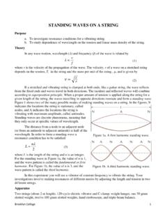
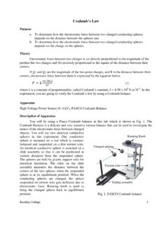
4 Substituting y/L for sin in the above equation, we get "#= l, or, rearranging, ='l#* (3) y1 W P o Fig. 2: single slit diffraction configuration. y-1 y-2 y2 q Brooklyn College 3 Figure below is a photograph of a single slit diffraction pattern on a screen using a red laser. Distance between the dark patterns of the same order, D can be measured the diffraction pattern to calculate the wavelength of the light used. Since the slits have a finite slit width in Double slit experiment, it is thoughtful idea to look back to Double slit interference pattern. Thus, practically, Double slit interference pattern will have single slit effect. As you will observe in this experiment, the real interference pattern will have interference pattern enveloped in diffraction pattern with evenly-spaced narrower bright fringes grouped in a few broader bands with decreasing intensity on both sides. The broader bands are because of the single slit diffraction . We can determine the slit width from the broader bands.
5 Figure 4: interference pattern of a Double slit, showing overlapped single slit diffraction pattern as well Central maxima due to single slit effect overlapped with interference pattern Fringes due to Double slit interference D1 Fig. 3. Photograph of a single slit diffraction pattern on a screen using a red laser D1 D2 D3 Brooklyn College 4 Running the experiment Part 1: Double slit interference 1. Open the simulator (wait 5 seconds for it to load). After viewing the wave fronts (tangents to spherical curves emanating from the 2 slits), uncheck the box show wave fronts , and click show interference pattern. After the pattern extends on the screen to the full length of the screen, click pause. Observe the interference pattern. After you observe the interference pattern, click show scale. The interference pattern and the scale do not show simultaneously, so the interference pattern will no longer be shown, but the lines of maxima show you the positions of the maxima (bright fringes).
6 Using the given values of d (slit distance: distance between the 2 slits), Dy on the screen between the central maxima and the 1st successive maxima, and L the distance to the screen, calculate the wavelength of the light l and compare with the value given by the simulator. Repeat using Dy = y2 y1 (the 2nd and the 1st maxima both on the upper side of o: the central maxima). 2. Now change the wavelength l in the simulator to 500 nm and repeat step 1. Part 2: single slit diffraction 1. Open the simulator ~duffy/HTML5 In the type of opening click single slit . Notice that the (default) color of light is red. The chosen wavelength l of red is between 635 and 700 nm. Keep all default values of slit width w (12 X 10-6m), and L (1m) distance to screen 2. Measure, on the simulator s graph, the width of the central maxima the Dy = y1 y -1, between the first minima on the right and the first minima on the left (notice that in the simulator y is called x and also the unit cm needs to be converted to m).
7 Using the slit width w , given by the simulator and L , the distance to the screen, calculate the wavelength, and compare with the chosen range for red. Repeat for Dy = y2- y1 (second minima and first minima both on the right side of the central maxima). Which eqn. should you use? 3. Repeat step 2 for green light, then for violet light. (Accepted range: for l green = 520 - 560 nm, for l violet = 400 - 450nm). 4. With violet light, decrease the slit width w to 10 m. Inspect what happens to the width of the central maxima. Can you explain why in terms of the equations given in the introduction? Questions 1. How would be the pattern on the screen if a thin wire on wide open slide is used instead of the thin opening (slit) in single slit diffraction ? 2. For a given pair of slits, how does the pattern alter if one switches from a higher- laser (say, red) to a lower- (say, green) laser? 3. What will happen in the two-slit pattern obtained in your experiment, (i) if the slit width (w) is reduced keeping the distance between the slits (d) same?
8 And (ii) if the distance between the slits (d) is reduced keeping the slit width (w) same? Explain with diagrams. 4. How would the pattern on the screen be with two-slit if another two-slit is overlapped perpendicularly? 5. What do you think will happen in the interference pattern if you keep adding slits at the same separation d? Brooklyn College 5 Data sheet Name: Group: Date experiment performed: Part 1: Double slit interference Distance between slits d =.. Distance from slits to screen, L = .. Table 1 Wavelength, l of light used (given by the simulator) = ..nm y1 y0 Dy l calculated y2 y1 Dy l calculated Average l calculated= .., compare to Table 2 Wavelength, l of light used (given by the simulator) = ..nm y1 y0 Dy l calculated y2 y1 Dy l calculated Average l calculated= .., compare to Part 2: single slit diffraction Slit width w = .. L distance from slit to screen=.
9 Table 3 Range of lred used = y1 y-1 Dy l calculated y2 y1 Dy l calculated Average l calculated = .. Does your calculation match with used range of l?.. Brooklyn College 6 Table 4 Range of lgreen used = y1 y-1 Dy l calculated y2 y1 Dy l calculated Average l calculated= .. Does your calculation match the range of lused? Table 5 Range of lviolet used = y1 y-1 Dy l calculated y2 y1 Dy l calculated Average l calculated= .. Does your calculation match the range of lused? Comment on decreasing the slit width w.