Transcription of Experiment 5: Polarization and Interference
1 INTRO TO EXPERIMENTAL PHYS-LAB 1493/1494/2699 Experiment 5: Polarization and Interference Nate Saffold Office Hour: Mondays, 5:30PM-6:30PM @ Pupin 1216 PHYS 1493/1494/2699: Exp. 5 Polarization and Interference2 Introduction Outline: Review of physics: waves of an EM wave and diffraction (double and single slit experiments) Polarization and Interference Experiment : of the apparati analysis Tips for the experiment3 Electromagnetic waves Electromagnetic wave = oscillating electric and magnetic fields An EM wave propagates in vacuum at the speed of light Electric and magnetic fields are always perpendicular to each other(James Clerk Pretty smart )PHYS 1493/1494/2699: Exp. 5 Polarization and Interference4 Polarization Polarization of a light wave = direction of oscillation of the electric field Every day light is usually unpolarized.
2 All directions of the electric field are equally probable. Linearly polarized light = the direction of oscillation at a particular point in space is always the sameUnpolarized beam of light moving perpendicularly to the screen. No preferred direction of oscillationLinearly polarized beam of light moving perpendicularly to the screen. Electric field points in one direction 1493/1494/2699: Exp. 5 Polarization and Interference5 Polarization by selective absorption White light (as from a light bulb) is usually unpolarized. Polarizer = material that selects one particular direction of oscillation of the incoming light If we place two linear polarizers in sequence then: one: it makes unpolarized light linearly polarized one: it determines which fraction of the incoming light arrives at the end of the apparatusUnpolarizedPolarized but half intensityPolarized and different intensityPHYS 1493/1494/2699: Exp.
3 5 Polarization and Interference6 Malus Law If we place two polarizers in sequence, the magnitude of the transmitted polarized electric field will depend on the angle between polarizers. This is how the electric field behaves when passing through two linear polarizers. What do we actually see?Electric field coming out of second polarizerElectric field coming out of first polarizerOrientation of first polarizerOrientation of second polarizerPHYS 1493/1494/2699: Exp. 5 Polarization and Interference7 Malus Law Our eyes cannot detect the electric field directly We only see its time average intensity Intensity = magnitude squared of the electric field From the formula in the previous slide we obtain the so-called Malus Law: Intensity coming out of second polarizerIntensity coming out of first polarizerRelative angle between the axes of the two polarizersPHYS 1493/1494/2699: Exp.
4 5 Polarization and Interference8 Malus Law The intensity coming out of the polarizers as a function of the angle between the two then looks like:=Iocos2 I=Iocos2 If the two polarizers are perpendicular to each other no light is transmittedPHYS 1493/1494/2699: Exp. 5 Polarization and Interference9 Interference An essential property of waves is the ability to get combined with other waves The result of this superposition can lead to a wave with greater or smaller amplitude This phenomenon is called interferenceMaxima superimposed to minimaMaxima superimposed to maximaThey cancel outThey add to each otherPHYS 1493/1494/2699: Exp. 5 Polarization and Interference10 Young's double slit Experiment Question: if light is a wave, what should we expect from it? Young's double-slit Experiment (1801): Pass light through two very narrow slits and observe pattern on distant screen.
5 Waves coming out of the two slits interfere and create a fringe pattern of bright and dark spotsPHYS 1493/1494/2699: Exp. 5 Polarization and Interference11 Young's double slit Experiment The pattern on the wall can be derived from optics We need to see how two rays from the two slits interfere with each otherMaxima correspond to bright spotsMinima correspond to dark spotsPHYS 1493/1494/2699: Exp. 5 Polarization and Interference12 Condition for a bright spot Let the screen be at a distance D from the slits. Let s take this distance much larger than the distance between slits (D>>d). Rays emerge almost parallel to each other. In order for both of them to end up on the same point (and hence interfere) one of the two must travel a slightly longer distance:Extra distance traveled by the second rayPHYS 1493/1494/2699: Exp.
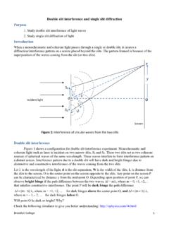
6 5 Polarization and Interference13 Condition for a bright spot We want a bright spot, constructive Interference In order for two maxima to overlap the difference in travel distance must be a multiple of the wavelength where m is an integer number and is the wavelength of incoming light Since D>>d we can use the small angle approximation:The distance of the m-th bright spot from the center is then:PHYS 1493/1494/2699: Exp. 5 Polarization and Interference14 Young's double-slit Experiment The pattern appearing in the double slit Experiment is due to the Interference effect However, in real life you will also have diffraction. Light phenomena will always be a combination of the two effectsPHYS 1493/1494/2699: Exp. 5 Polarization and Interference15 Young's double-slit Experiment The pattern appearing in the double slit Experiment is due to the Interference effect However, in real life you will also have diffraction.
7 Light phenomena will always be a combination of the two effects Diffraction = Spread of waves around an obstacle or slit Only relevant when the obstacle size is comparable to the wavelength Wave behaves as if it was interfering with itself PHYS 1493/1494/2699: Exp. 5 Polarization and Interference16 If diffraction is made around a single slit the intensity is given by:Diffraction intensity patterna = single-slit width = wavelength = angle on the screenPHYS 1493/1494/2699: Exp. 5 Polarization and Interference17 Single-slit minima occur at: Again, using small angle approximation, the minima occur at: If diffraction is made around a single slit the intensity is given by:Diffraction intensity patterna = single-slit width = wavelength = angle on the screenPHYS 1493/1494/2699: Exp. 5 Polarization and Interference18 Single-slit minima occur at: Again, using small angle approximation, the minima occur at: If diffraction is made around a single slit the intensity is given by:Diffraction intensity patterna = single-slit width = wavelength = angle on the screenCareful!
8 The expression is similar to that for the double slit but now it s for dark spots, not bright onesPHYS 1493/1494/2699: Exp. 5 Polarization and Interference19 The ExperimentPHYS 1493/1494/2699: Exp. 5 Polarization and Interference20 Goals To study the Polarization properties of EM waves Polarize a beam of white light Verify Malus' Law: measure intensity of white light when light travels through two polarizers at an angle with respect to each other: To study the Interference and diffraction phenomena Use a He-Ne laser as coherent light source (single wavelength) Determine of the laser from the double-slit Interference pattern Determine of the laser from single-slit diffraction patternPHYS 1493/1494/2699: Exp. 5 Polarization and Interference21 EquipmentMeasures the (relative) intensitySuper precise scientific generator of unpolarized white a light you to change the reading point on the screen by fractions of 1mmPHYS 1493/1494/2699: Exp.
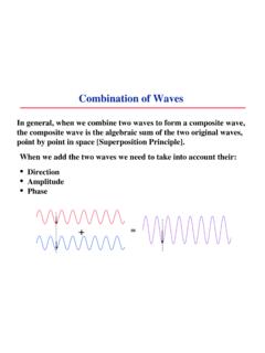
9 5 Polarization and Interference22 Part 1: Malus law Equipment: Incandescent light source (source of EM waves) Polarization filters Photometer (measures intensity of outgoing EM waves) For Polarization : Incandescent light is a source of unpolarized EM waves E-field has no preferred direction Place a polarizer in front of the incandescent light sourceOutgoing light should be polarized!PHYS 1493/1494/2699: Exp. 5 Polarization and Interference23 Part 1: Malus Law Polarizers in sequence Place two polarizers in front of the light source Measuring intensity of light: Align the axis of both polarizers such that they are parallel to each other. Measure and record intensity. Rotate the second polarizer in 5-10 degree increments with respect to the first one. Record intensity at each stepPHYS 1493/1494/2699: Exp. 5 Polarization and Interference24 Part 1: Malus' Law According to Malus law: You will have a set of pairs Linearize the data by plotting vs.
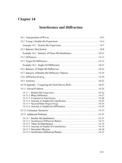
10 Perform a linear fit and find slope and intercept (w/ errors!). Are they what you expect? Plot residuals to check for consistency of the fitPHYS 1493/1494/2699: Exp. 5 Polarization and Interference25 Part 2: double-slit Experiment Procedure: Mount laser in far end of optical bench. Mount slit set C (double-slit) in front of the laser beam. Observe double-slit intensity pattern with a white piece of paper. Use linear translator with fiber optic attached to measure intensity at different positions in the transverse directionPHYS 1493/1494/2699: Exp. 5 Polarization and Interference26 Part 2: double-slit Experiment Record the position of maxima Plot xm vs. order number (m) Perform a linear fit Use slope to estimate the wavelength of the laser Remember to propagate uncertainties! If you are careful enough the results can be fairly accurate:PHYS 1493/1494/2699: Exp.