Transcription of Interference and difiraction - Harvard University
1 Chapter 9 Interference and diffractionCopyright 2010 by David Morin, 1, June 25, 2010)This file contains the Interference and diffraction chapter of a potential book on Waves, designedfor college this chapter we ll study what happens when waves from two or more sources exist at agiven point in space. In the case of two waves, the total wave at the given point is the sumof the two waves. The waves can add constructively if they are in phase, or destructively ifthey are out of phase, or something inbetween for other phases. In the general case of manywaves, we need to add them all up, which involves keeping track of what all the phasesare. The results in this chapter basically boil down to (as we ll see) getting a handle on thephases and adding them up properly. We won t need to worry about various other wavetopics, such as dispersion, polarization, and so on; it pretty much all comes down to results in this chapter apply to any kind of wave, but for convenience we ll generallywork in terms of electromagnetic outline of this chapter is as follows.
2 In Section we do the warm-up case of twowaves interfering. The setup consists of a plane wave passing through two very narrow(much narrower than the wavelength of the wave) slits in a wall, and these two slits may beconsidered to be the two sources. We will calculate the Interference pattern on a screen thatis located far away. We ll be concerned with this far-field limit for most of this chapter,with the exception of Section In Section we solve the general case of interferencefromNnarrow slits. In addition to showing how the phases can be added algebraically, weshow how they can be added in an extremely informative geometric manner. In Section switch gears from the case of many narrow slits to the case of one wide slit. The word diffraction is used to describe the Interference pattern that results from a slit with non-negligible width. We will see, however, that this still technically falls into the category ofNnarrow slits, because one wide slit can be considered to be a collection of a large (infinite)number of narrow slits.
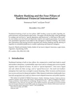
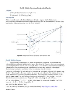
3 In section we combine the results of the two previous sectionsand calculate the Interference pattern fromNwide slits. Finally, in Section we drop theassumption that the screen is far away from the slit(s) and discuss near-field interferenceand diffraction. This case is a bit more complicated, but fortunately there is still a nicegeometric way of seeing how things behave. This involves a very interesting mathematicalcurve known as theCornu 9. Interference AND Two-slit interferenceConsider a plane wave moving toward a wall, and assume that the wavefronts are parallel tothe wall, as shown in Fig. 1. If you want, you can consider this plane wave to be generated plane wavewallFigure 1by a point source that is located a very large distance to the left of the wall. Let there betwo very small slits in the wall that let the wave through. (We ll see in Section thatby very small, we mean that the height is much smaller than the wavelength.) We reassuming that the slits are essentially infinite in length in the direction perpendicular to thepage.
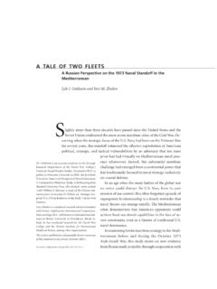
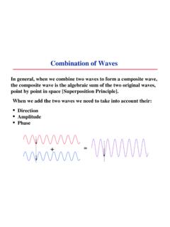
4 So they are very wide but very squat rectangles. Fig. 2 shows a head-on view fromwallwallslits(view from distant source)wall extends infinitely in both directionswallwall extends infinitely in both directionsFigure 2the far-away point Huygens principle we can consider each slit to be the source of acylindricallypropa-gating wave. It is a cylindrical (and not spherical) wave because the wave has no dependencein the direction perpendicular to the page, due to the fact that it is generated by a line source(the slit). If we had a point source instead of a line source, then we would end up witha standard spherically propagating wave. The reason why we re using a line source is sothat we can ignore the coordinate perpendicular to the page. However, having said this, thefact that we have a cylindrical wave instead of a spherical wave will be largely irrelevant inthis chapter. The main difference is that the amplitude of a cylindrical wave falls off like1/ r(see Section [to be added] in Chapter 7) instead of the usual 1/rfor a spherical for reasons that we will see, we can usually ignore this dependence.
5 In the end, sincewe re ignoring the coordinate perpendicular to the page, we can consider the setup to bea planer one (in the plane of the page) and effectively think of the line source as a pointsource (namely, the point on the line that lies in the page) that happens to produce a wavewhose amplitude falls off like 1/ r(although this fact won t be very important).The important thing to note about our setup is that the two sources arein phasedueto the assumption that the wavefronts are parallel to the that instead of thissetup with the incoming plane wave and the slits in a wall, we could of course simply havetwo actual sources that are in phase. But it is sometimes difficult to generate two wavesthat are exactly in phase. Our setup with the slits makes this automatically be the the two waves propagate outward from the slits, they will interfere. There will beconstructive Interference at places where the two waves are in phase (where the pathlengthsfrom the two slits differ by an integral multiple of the wavelength).
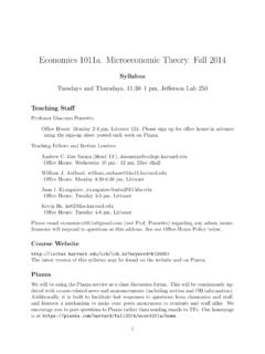
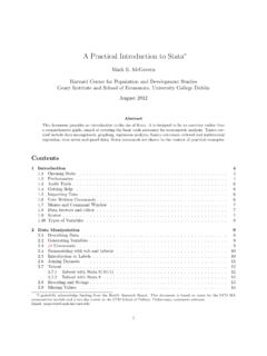
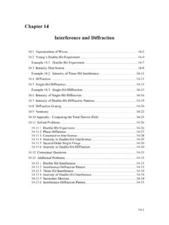
6 And there will bedestructive Interference at places where the two waves are 180 out of phase (where thepathlengths from the two slits differ by an odd multiple of half of the wavelength). Forexample, there is constructive Interference at pointAin Fig. 3 and destructive interferenceABFigure 3at is the Interference pattern on a screen that is located very far to the right of thewall? Assume that the screen is parallel to the wall. The setup is shown in Fig. 4. Thedistance between the slits isd, the distance to the screen isD, the lengths of the two pathsto a given pointParer1andr2, and is the angle that the line toPmakes with thenormal to the wall and screen. The distancexfromPto the midpoint of the screen is thenx=Dtan .1 Problem shows how things are modified if the wavefronts aren t parallel to the wall. This is done inthe context of theN-slit setup in Section The modification turns out to be a trivial TWO-SLIT INTERFERENCE3wallscreenPdxS1r1r2S2D essentiallyparallelFigure 4In finding the Interference pattern on the screen, we will work in the so-calledfar-fieldlimit where the screen is very far away.
7 (We ll discuss thenear-fieldcase in Section )2 The quantitative definition of the far-field limit isD d. This assumption thatDis muchlarger thandleads to two important facts. IfD d, then we can say that the two pathlengthsr1andr2in Fig. 4 are essentiallyequal in amultiplicativesense. That is, the ratior1/r2is essentially equal to 1. Thisfollows from the fact that the additive difference|r1 r2|is negligible compared withr1andr2(because|r1 r2|can t be any larger thand, which we are assuming isnegligible compared withD, which itself is less thanr1andr2). Thisr1/r2 1 factthen tells us that the amplitudes of the two waves at pointPfrom the two slits areessentially equal (because the amplitudes are proportional to 1/ r, although the exactpower dependence here isn t important). IfD d, then we can say that ther1andr2paths in Fig. 4 are essentially parallel,and so they make essentially the same angle (namely ) with the normal. The parallelnature of the paths then allows us to easily calculate theadditivedifference betweenthe pathlengths.
8 A closeup of Fig. 4 near the slits is shown in Fig. 5. The differenceto screen far awaydS1S2 d sin Figure 5in the pathlengths is obtained by dropping the perpendicular line as shown, so we seethat the differencer2 r1equalsdsin . The phase difference between the two wavesis thenk(r2 r1) =kdsin =2 dsin = 2 dsin .(1)In short,dsin / is the fraction of a cycle that the longer path is ahead of the :We found above thatr1is essentially equal tor2in amultiplicativesense, but not inanadditivesense. Let s be a little more explicit about this. Let be defined as the difference, r2 r1. Thenr2=r1+ , and sor2/r1= 1 + /r1. Sincer1> D, the second term here is lessthan /D. As we mentioned above, this quantity is negligible because can t be larger thand, andbecause we re assumingD d. We therefore conclude thatr2/r1 1. In other words,r1 r2in amultiplicative sense. This then implies that the amplitudes of the two waves are essentially , the phase difference equalsk(r2 r1) = 2 (r2 r1)/ = 2 / . So if is of thesame order as the wavelength, then the phase difference isn t negligible.
9 Sor2isnotequal tor12 The fancier terminology for these two cases comes from the people who did pioneering work in them:theFraunhoferlimit for far-field, and theFresnellimit for near-field. The correct pronunciation of Fresnel appears to be fray-NELL, although many people say 9. Interference AND DIFFRACTIONin anadditivesense. To sum up, the multiplicative comparison ofr2andr1(which is relevant forthe amplitudes) involves the comparison of andD, and we know that /Dis negligible in thefar-field limit. But the additive comparison ofr2andr1(which is relevant for the phases) involvesthe comparison of and , and may very well be of the same order as . Having found the phase difference in Eq. (1), we can now find the total value of the waveat pointP. LetAPbe the common amplitude of each of the two waves atP. Then up toan overall phase that depends on when we pick thet= 0 time, the total (complex) wave atPequalsEtot(P) =APei(kr1 t)+APei(kr2 t)=AP(eikr1+eikr2)e i t.(2)Our goal is to find the amplitude of the total wave, because that (or rather the square of it)yields the intensity of the total wave at pointP.
10 We can find the amplitude by factoringout the average of the two phases in the wave, as (P) =AP(eik(r1 r2)/2+e ik(r1 r2)/2)eik(r1+r2)/2e i t= 2 APcos(k(r1 r2)2)ei(k(r1+r2)/2 t)= 2 APcos(kdsin 2)ei(k(r1+r2)/2 t),(3)where we have usedk(r2 r1) =kdsin from Eq. (1). The amplitude is the coefficient ofthe exponential term, so we see that the total amplitude atPisAtot(P) = 2 APcos(kdsin 2) Atot( ) = 2A( ) cos(kdsin 2),(4)where we have rewrittenAPasA( ), andAtot(P) asAtot( ), to emphasize the dependenceon . Note that the amplitude at = 0 is 2A(0) cos(0) = 2A(0). Therefore,Atot( )Atot(0)=A( )A(0)cos(kdsin 2)(5)The intensity is proportional to the square of the amplitude, which givesItot( )Itot(0)=A( )2A(0)2cos2(kdsin 2)(6)Since the amplitude of a cylindrically propagating wave is proportional to 1/ r, we haveA( )A(0)=1/ r( )1/ r(0)= r(0)r( )= DD/cos = cos .(7)Therefore,Itot( )Itot(0)= cos cos2(kdsin 2)= cos cos2( dsin ).(8) TWO-SLIT INTERFERENCE5 This result holds for all values of , even ones that approach 90.