Transcription of Doug’s Guide to the XTS 3000 Radio - akardam.net
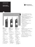
1 Batdude s Guide for theXTS 3000 - XTS 5000and astro Digital Saber3 September 2006 Revised 3 November 2006As I sat down today to install a NTN8255 DES-OFB module into an XTS 3000 portable Radio , I thought some of you would appreciate an informal walkthrough of the tips to disassemble the Radio and get it back together again without any damage. I can t count how many times I ve seen radios in the used market that have case damage due to improper disassembly. The key to the entire process is this:Without this tool, I can guarantee that you will either split the end of the case plastic, as shown in the below picture, or gouge/destroy the protective is an actual Radio that I purchased at course, I ll show you this, just because Ithink it s indicative of how about 80% of thepeople out there open up their radios:Okay, you have finally ordered your handy-dandy white opener tool, Motorola part number 6685833D01(cost is about $ ) and you re ready to crack the case.
2 I can give you the rhetoric about ESD safety now obviously what you are seeing here is on the border of ESD-unsafe. However, I m not sitting here rubbing my cat while my feet are on the carpet either. This procedure should (of course) be conducted at an ESD approved workbench while wearing a wrist strap. Note how the hinge of the tool captures the SURE THE ANTENNA HAS BEEN REMOVED BEFORE DOING THIS!After you get the front shield separated from the chassis, you ll have the Radio disassembled to this point (note the o-ring is intact and undamaged):Gently wiggle the chassis free and lift upward and away from the front shieldSeparating the front shield flex from the chassis can be tricky, but you ll get the hang of it you can use your thumb to pop the flex connector off:The white part here is the connector, the black is the plastic flex support very gently pry downward on the black support and the connector will unmate with little or no things in this picture one is the connector type this is a B series connector (notice how wide it is with the male plug in the center).
3 The second item is the green universal connector plug the lip at the bottom of this retainer. This is a modification that is required to prevent wear on the flex. See the next Connector RetainerOld style on the left, new on theright. Motorola kit 4205582Z07 was aretrofit for the old style. You will have tocall parts ID as this doesn t appear to bea valid part number Series vs. B Series Housings A Series radios ( H09 RDH9PW7AN) use a different controllerboard (NCN6128) that has a different plug on it for connecting thefront housing. This is CRUCIAL when ordering replacement partsfor your Radio ! In the below picture, the B series is on the , back on the below picture, you see the Radio with the front shield completely Flex retainer bracket has two snaps that must be pried upward to removeOne of the most common assembly errors is right here. This brown finger is part of the flex for the LCD.
4 There is a slot in the retainer to allow this finger to stick out and be compressed against the frame during are the three mounting posts for the LCD protector (black rubber piece). Make sure the red plastic is on there as it helps retain the LCD securely in is a cutout in the Keypad shield that is for the rubber tit on the LCD flex make sure it s seated right!I normally just use the plastic special tool for this, but a small flat blade screwdriver works just as well. Note the finger of the LCD flex sticking is the keypad flex retainer, again a small flat blade works well here are four small retainers that must be released to remove the keypadFlex assembly. Once removed you can remove the entire keypad flex assembly and set it aside. Note the flex retainer is completely released from the chassis. There is a small cutout that forms a notch that holds the NCN6167 controller board in place.
5 If you gently lift the controller board up from the BOTTOM of the Radio , it will slip right out of the Radio . Ensure the top of the controller board engages this retainer notch during reassembly!Nice view of the NCN6167 controller board and LCD assembly after partial by the that controller board is about $ and the LCD is about $ so BE CAREFUL!(FYI, this board stores your HOST firmware).This is your VOCODER. It s not a VOCON It s a VOCODER. This is where your DSP firmware is stored. Note that it s installed upside two header connectors route signals between the controller board, the vocoderand the RF board. INGENIOUS! They are keyed to prevent installing them the wrong way but you need to watch reassembly to ensure that they haven t that the NCN6167 Controller board has been removed, this is what you ll see:The NTN8250 VOCODERBe careful don t fry it or drop it current replacement cost is around $ the keying lugs on these connectors they re supposed to be sailor proof be sure you put them in right!
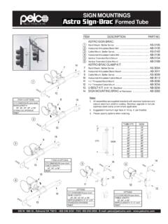
6 Removing the RF not required for my but shown to you!There is one retainer clip on the left side that must be is the same style clip as the two detents need to be popped on the right hand side to remove the RF are two small detents that must be disengaged to remove the RF board shield. Note the blueRF cable be VERY careful with this cable it s two ended and connects the RF board to the antenna connector it s VERY EASILY may have to use your small flat blade screwdriver to GENTLY pry the RF board shield BE CAREFUL!RF Shield RF board is removed by lifting it from the LEFT side (long silver can) and tilting it upward to free the two retainers from their detents in the chassis (yellow circles).. if you are removing the RF board completely, use a small pair of hemostats or fine needlenose pliers to remove the RF cable from it s socket on the RF What I was really here is a side view of the secure module and it s mounting tray.
7 Note the gap between the secure module and the retainer THIS IS NOT INSTALLED CORRECTLY and must be fixed before the secure module in the retainer tray as shown. There are notches in this tray that will retain the board. Lay it flat as shown and then slide it to the left and it will be under the notches. DO NOT FORCE IT and DO NOT bend the metal retainer!Notice how the secure board lays flat in the mounting tray and note the bend in the tray (the V shape) this is the correct layout!There are two detents on the LEFT HAND SIDE that must be engaged FIRST. Once they have snapped into place, use your screwdriver to GENTLY press down on the right side of the RETAINER (NOT THE BOARD!) and it will snap into place. Once this is done, check your 2 interconnect header connectors to make sure they are still oriented properly installed secure note that the metal secure module retainer board is snug against the you re-install the Controller board (noting the notch at the top of the ) you can gently press down on the yellow caps on top of the board to mate the secure module to the controller Idiot CheckOnce you have the controller board mated to the secure module and properly reseated into the chassis, check to make sure you can see the posts on the header connectors sticking through their corresponding holes in the board.
8 This is your last chance before final assembly to correct an incorrectly seated header connector!Install the keypad flex and shield are four retainers that must engage the engage the Keypad flex LCD DisplayThe XTS 3000 LCD has a very serious weak link the flex. You must be extremely careful during installation and removal or you will tear it and ruin the assembly. Best method is to lay it face down and align the flex / flex retainer and then snap into place, then fold the display over and mate it to the 3 red-tipped binding posts. Ensure the protrusion on the bottom of the LCD protective rubber correctly mates with the cutout on the keypad CLEAN YOUR FINGERPRINTS OFF THE LCD!! (pet peeve, sorry)LOOK MOM! My o-ring isn t torn up!Note the rubber tit at the bottom of the LCD is engaged in the keypad flex shield and the finger is sticking out from the display Insert the chassis into the top of the front The two upper metal tabs on the casting will slide UNDER the yellow lip below the MOTOROLA keep pushing the casting upwards into the front sure the o-ring is properly seated along the left and right of the frame and you ll end up with the picture on the left Ready for the final seat into the trick that I ve used is to turn the tool around BACKWARDS and very gently pry the case outward while simultaneously pushing down on the Radio This makes the o-ring seat properly EVERY TIME!
9 Note that the o-ring is NOT visible from the outside and that there is ZERO DAMAGE to the bottom of the front Done RIGHT!And the final Damn KnobsThe frequency knob inserts on the 3000 and 5000 are *NOT* the same, neither is the sticker that goes on the insert! Alas, you use the same technique to remove and install them. Here are some pictures that can help you with this task. I discourage you from reusing the inserts as they are very easily so easy that the first test I do when I examine a Radio for purchase is to gently pull upwards on the channel select (frequency) knob to see if it s been you d be amazed how many come off in your white plastic piece is commonly referred to as an insert ..the manual calls it an insert retainer . The volume insert is the same for both the 3000 and pry out the fingers from the insert and pry it takes a few differences XTS 3000 Channel select insert P/N 4305373Z01 Channel escutcheon P/N 1305374Z01 Volume insert P/N 4305372Z01 XTS 5000 Channel select Insert P/N 4305373Z02 Channel escutcheon P/N 1505374Z03 Volume insert P/N 4305372Z01 Note: Same part some on the 5000 The XTS 5000 is VERY similar, yet very different from the XTS 3000 series radios.
10 It s obvious from the internals that they learned some valuable lessons from the design of the 3000 . Gone are the metal retainers that secure the LCD and keypad They ve been replaced with high density connectors that are much easier to install and remove. One of the most glaring differences between the two radios is that the XTS 5000 only uses two circuit boards: the VOCON and the RF board. Gone is the XTS3000 vocoder board it s been completely incorporated into the VOCON. (VOcoder CONtroller = VOCON)The removal of the front shield on the XTS 5000 is exactly the same as the XTS 3000 . The special tool is the previously covered 6685833D01. The front shield flex plug from the housing to the VOCON is a little smaller on the 5000, but the technique of front shield removal is the flex plugFront Shield flex plugKeypadflex plugNice shot of the LCD connector. The rubber locator pad surrounding the LCD is only secured on two posts on the 5000 the 3000 uses three is the old style NTN4563 VOCON.