Transcription of DP14HM Commercial - daikinac.com
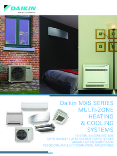
1 SS- 9/163 - 5 TON THREE-PHASEPACKAGED HEAT PUMPS14 SEERC ooling Capacity: 34,400 - 58,000 BTU/hHeating Capacity: 33,200 - 57,000 BTU/hDP14HM Commercial ContentsNomenclature ..2 Product Specifications ..3 Expanded Cooling Data ..4 Expanded Heating Data ..10 Heat Kit Electrical Data ..11 Airflow Data ..12 Dimensions ..13 Wiring Diagram ..14 Accessories ..16* Complete warranty details available from your local distributor or manufacturer s representative or at Standard Features Energy-efficient compressor with internal relief valve Fully charged with R-410A chlorine-free refrigerant MultiI-speed EEM blower motor Convertible airflow: horizontal or downflow Copper tube / aluminum fin condenser coil All-aluminum evaporator coils Totally enclosed, permanently lubricated condenser fan motor Electric heat kit available as a field-installed accessory AHRI Certified; ETL Listed Two-stage cooling on 5-ton units Cabinet Features Heavy-gauge galvanized-steel cabinet Attractive Nickel Gray powder-paint finish Fully insulated blower compartment with convenient access panels Louvered condenser coil protection One footprint.
2 Two DP14HM3643AA123,4567,89101112 BrandEngineeringD - DaikinMinor revisionsProduct TypeEngineeringP - PackagedMajor revisionsSEERV oltage14 - 14 SEER3-208/230V, Three-Phase 60 HzUnit TypeRefrigerantH - Heat Pump4 - R-410AC - Air ConditionerG - Gas/ElectricTonnage Nominal36 - 3 tonsConfiguration48 - 4 tonsM - Multi-position60 - 5 tonsNomenclature60 - 5 *DP14HM4843A*DP14HM6043A*Cooling CapacityTotal BTU/h34,40048,00058,000 Sensible BTU/h26,20036,40042,500 seer / EER14/1114/1114/11 Decibels817980 AHRI #s995630499563059956306 Heating CapacityBUT/h (47 F)33,20045,50057, (47 F) (17 F)19,00026,60031, (17 F) MotorTypeEEMEEMEEMW heel (DxW)10 x 910 x 910 x 9 Nominal Cooling CFM1,2001,6001,850 / / / --No. of Speeds555 Horsepower - RPM - 1,050 - 1,0501 - 1,050 Evaporator CoilFace Area (ft ) Deep/ Fin per Inch4 / 144 / 144 / 14 Drain Size (NPT) " " "Refrigerant Charge (oz.)115153180 Condenser Fan / CoilHorsepower - RPM - 830 - 1,075 - 1,075 FLA/ / / / Diameter / # Fan Blades22 / 422 / 322 / 3 Face Area (ft ) Deep/ Fin per Inch2 / 162 / 162 / 16 CompressorQuantity / Type1 / Scroll1 / Scroll1 / ScrollStageSingleSingle2 Stage Compressor RLA/ / / 110 Electrical DataVoltage/ Phase/ Frequency208-230/3/60208-230/3/60208-230 /3/60 Total Unit Circuit Overcurrent Protection225 amps35 amps45 ampsShipping Weight (lbs)400475495 Wire size should be determined in accordance with National Electrical Codes.
3 Extensive wire runs will require larger wire sizes. May use fuses or HACR-type circuit breakers of the same size as : Always check the S&R plate for electrical data on the unit being Ambient Temperature65 F75 F85 F95 F105 F115 FEntering Indoor Wet Bulb TemperatureIDB PR242260275-271292308-309332351-35137839 9-395426449-437470496-LO PR239258272-269289305-306329347-34837539 5-392421445-433466492-LO PR232250264-261280296-296319337-33836338 4-380409432-420452477-LO : Entering Indoor Dry Bulb TemperatureShaded area reflects ACCA (TVA) conditionsAmps = Unit amps (Comp.+ Evaporator + Condenser fan motors)High and low pressures are measured at the liquid and suction access fittings kW = Total system powerExpanded Cooling Data DP14HM3643A** Ambient Temperature65 F75 F85 F95 F105 F115 FEntering Indoor Wet Bulb TemperatureIDB : Entering Indoor Dry Bulb TemperatureShaded area reflects AHRI conditionsAmps = Unit amps (Comp.)
4 + Evaporator + Condenser fan motors)High and low pressures are measured at the liquid and suction access fittings kW = Total system powerExpanded Cooling Data DP14HM3643A** (cont.) Ambient Temperature65 F75 F85 F95 F105 F115 FEntering Indoor Wet Bulb TemperatureIDB PR250269284-280301318-318343362-36339041 2-408439464-451485512-LO PR247266281-277298315-315339358-35938640 8-404435459-446480507-LO PR240258272-269289306-306329348-34837539 6-392422445-433466492-LO : Entering Indoor Dry Bulb TemperatureShaded area reflects ACCA (TVA) conditionsAmps = Unit amps (Comp.+ Evaporator + Condenser fan motors)High and low pressures are measured at the liquid and suction access fittings kW = Total system powerExpanded Cooling Data DP14HM4843A* Ambient Temperature65 F75 F85 F95 F105 F115 FEntering Indoor Wet Bulb TemperatureIDB : Entering Indoor Dry Bulb TemperatureShaded area reflects AHRI conditionsAmps = Unit amps (Comp.+ Evaporator + Condenser fan motors)High and low pressures are measured at the liquid and suction access fittings kW = Total system powerExpanded Cooling Data DP14HM4843A* (cont.
5 Ambient Temperature65 F75 F85 F95 F105 F115 FEntering Indoor Wet Bulb TemperatureIDB PR258277293-289311329-329354374-37540342 6-421453479-466501529-LO PR255275290-286308325-326350370-37139942 1-417449474-461496524-LO PR247266281-278299316-316340359-36038740 9-405435460-447481508-LO : Entering Indoor Dry Bulb TemperatureShaded area reflects ACCA (TVA) conditionsAmps = Unit amps (Comp.+ Evaporator + Condenser fan motors)High and low pressures are measured at the liquid and suction access fittings kW = Total system powerExpanded Cooling Data DP14H60M43A* Ambient Temperature65 F75 F85 F95 F105 F115 FEntering Indoor Wet Bulb TemperatureIDB : Entering Indoor Dry Bulb TemperatureShaded area reflects AHRI conditionsAmps = Unit amps (Comp.+ Evaporator + Condenser fan motors)High and low pressures are measured at the liquid and suction access fittings kW = Total system powerExpanded Cooling Data DP14H60M43A* (cont.) **Outdoor Ambient PR39137536134533733031830529227926826125 7247237228220212LO PR13412511710710197908072645753514337312 721 Above information is for nominal CFM and 70 degree indoor dry bulb.
6 Instantaneous capacity listed. High pressure is measured at the liquid line access fitting. Amps Unit amps (comp.+ evaporator motor + condenser fan motor) Low pressure is measured at the compressor suction access *Outdoor Ambient PR38737135634133332631430128927626525825 4244235225217209LO PR12912011210397938677696254504941353026 21DP14HM6043A*Outdoor Ambient PR42640939337636736034633231830429228528 0269259248239231LO PR12611711010195928475686153494840352926 20 Above information is for nominal CFM and 70 degree indoor dry bulb. Instantaneous capacity listed. High pressure is measured at the liquid line access fitting. Amps Unit amps (comp.+ evaporator motor + condenser fan motor) Low pressure is measured at the compressor suction access Heating & Heat Kit UsageCircuit #1 Actual kW / BTU@ 240 VMCA MOD DP14HM3643** / / 4560 / / 51,000DP14HM4843** / / 4560 / / 51,000 HKR3-20B51 / 5560 / / 66,500DP14HM6043** / / 4560 / / 51,000 HKR3-20B51 / 5560 / / 66,500 Minimum Circuit Ampacity @ 208 / 240 V Maximum Overcurrent Protection device @ 208 / 240 V* Revision level that may or may not be designatedC Circuit Breaker optionHeat Kit Electrical Data (Blower Only, Heat Mode)
7 * / T3230 CFM127812141182112910721013950853788 Watts221218232245253264265275272T4 / T5230 CFM160415601507146814151364132112761218 Watts396402408424426423444454454 DownshotPosition T1230 CFM809730623542485441---------Watts73859 298107112---------T2 / T3230 CFM12841223117510971031974871804761 Watts220227241247255262272277285T4 / T5230 CFM157815391498145213961332127912241161 Watts401409421425438439452453455DP14HM48 43* / T3230 CFM172316371598155415091467142013611295 Watts372370381390404411420427441T4 / T5230 CFM201219651912187118091770174116911635 Watts578593599606610627626634638 DownshotPosition T1230 CFM115510741023969896805755667626 Watts153156169180195205216226230T2 / T3230 CFM167015961558148414671383133912591168 Watts383392399408419434436447449T4 / T5230 CFM194918811853179217531699162115611522 Watts603607608616622626648650645DP14HM60 43* / T3230 CFM193518851848180917551705165916161567 Watts498512515520541549559567569T4 / T5230 CFM223221882144208720352017196319261869 Watts805795790827830842864864848 DownshotPosition T1230 CFM134712931236118411171054996934871 Watts242251268276290305321330348T2 / T3230 CFM182717801739168316331588151814621404 Watts529538548557557576578604601T4 / T5230 CFM211120572030197919471957192218681818 Watts835843846852870959956960966 Airflow " D" H" 16"32 "DP14 HMMFR102(for medium models)16 x 25 x 2 1DP14HM4843475142 18"40"DP14HM6043475142 18"40"DP14 HMMFR103(for large models)20 x 25 x 2 is subject to change.
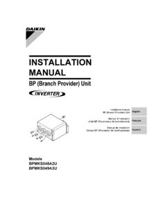
8 Always refer to the wiring diagram on the unit for the most up-to-date wiring. WarningHigh Voltage: Disconnect all power before servicing or installing this unit. Multiple power sources may be present. Failure to do so may cause property damage, personal injury, or death. Wired Diagram DP14HM36/4843 WIRECODEBK BLACKBL BLUEBR BROWNGR GREENOR ORANGEPU PURPLERD REDWH WHITEYL YELLOWFACTORYWIRING LINE VOLTAGE LOW VOLTAGE OPTIONAL HIGH VOLTAGEFIELDWIRING HIGH VOLTAGE LOW VOLTAGE3 CONTROL BOX240224V208 TRC1 PUWHBRBLROW2W1 CYT2T1L1 GNDCL2 BKRDRDBKBKLVJBFCCFPUYLBKBKRVCBKCOMPT3T1T 2 CMBRPUBKLPSDFTRDYLBKYLBLHPSBRPUGBLLVTBOR WHWHBLPKYLBKGRBKPU101112789456321 BRGRGR123654987121110 PUPUBRBRYLPLM-PGRPUBK1236 54987121110 BRBRBRYLYLBKBKPUPUPUBKPURDRDRDBRBLPUBLBL RDBLBLWHWHWHPLF-CPUPUPKBLBKPS2 CCRCYYR-PS1R-DFTDFT0 CNTCCRHVDRLVDRWC-RV0-RV0DF2DF1 RDCPUBKORRDSEE NOTE 4 YLYLSEENOTE341 PLF-H5623789 BLBRWHGRBKPUYLBLWHCLGN123EM45GR101112789 456321 PLM-BSEE NOTE 2 BLGRYLWH23 SEE NOTE 2 SEE NOTE 3 EMTR208-230208-230/3/60 SUPPLY VOLTAGECCOMPT1T3T1T2L1DF1 CFFCCMHVDRT2 CDF21N312 LGCHCHSRW2OW1 YGC456 PLFEM1 CHPSCTHERMOSTAT2324 VDCDFTYCRRVCLPSCNTR-PS1PS2 RWOR-DFTDFTO-RVC-RVSEE NOTE 5 SEE NOTE
9 2L2 NOTES:1. REPLACEMENT WIRE MUST BE SAME SIZE AND TYPE INSULATION AS ORIGINAL (AT LEAST 105 C) USE COPPER CONDUCTOR TO CHANGE EVAPORATOR MOTOR SPEED MOVE YELLOW AND WHITE LEADS FROM EM"2" AND "3" TO "4" AND "5". IF BOTH LEADS ARE ENERGIZED, THE HIGHER SPEED SETTING IS FOR 208 VOLT TRANSFORMER OPERATION MOVE BLACK WIRE FROM TERMINAL 3 TO TERMINAL 2 ON USE COPPER CONDUCTORS ONLY ++ USE CLASS 2 WIRE5. CRANKCASE HEATER AND CRANKCASE HEATER SWITCH FACTORY EQUIPPED WHEN REQUIRED. SEE UNIT RATING PLATE FOR TYPE AND SIZE OF OVER CURRENT PROTECTION208-230/3/60 0140G04457-BCOMPONENT LEGENDC CONTACTORCCR COMPRESSOR CONTACTOR RELAYCH CRANKCASE HEATERCHS CRANKCASE HEATER SWITCHCM CONDENSER MOTORCOMP COMPRESSORDC DEFROST CONTROLDFT DEFROST THERMOSTATEM EVAPORATOR MOTORFC FAN CAPACITORGND EQUIPMENT GROUNDHPS HIGH PRESSURE SWITCHHVDR HIGH VOLTAGE DEFROST RELAYLPS LOW PRESSURE SWITCHLVDR LOW VOLTAGE DEFROST RELAYLVJB LOW VOLTAGE JUNCTION BOXLVTB LOW VOLTAGE TERMINAL BLOCKPLF-C FEMALE PLUG/CONNECTOR - CONTROLPLF-H FEMALE PLUG/CONNECTOR - HEAT KITPLF-P FEMALE PLUG/CONNECTOR - PESSURE SWITCHPLM-B MALE PLUG/CONNECTOR - BLOWERPLM-P MALE PLUG/CONNECTOR - PRESSURE SWITCHRVC REVERSING VALVE COILSA START ASSISTTR TRANSFORMERCHRDCHSGRBKPURDBKPLF-PBKSEE
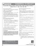
10 NOTE 5208/230/3/60 THERMOSTAT ++ is subject to change. Always refer to the wiring diagram on the unit for the most up-to-date wiring. WarningHigh Voltage: Disconnect all power before servicing or installing this unit. Multiple power sources may be present. Failure to do so may cause property damage, personal injury, or death. Wired Diagram DP14HM604323 SEE NOTE 2 SEE NOTE 3 EMTR208-230208-230/3/60 SUPPLY VOLTAGECCOMPT1T3T1T2L1DF1 CFFCCMHVDRT2 CDF2L21L312RW2OW1Y1 GCEM1 CCSRSEE NOTE 5 THERMOSTATNG23 CHSCHY2 CSOLHPS24 VDCDFTYCRRVCLPSCNTR-PS1PS2 RWOR-DFTO-RVC-RVDFT456 PLFSEE NOTE 23 CONTROLBOX240224V208 TRC1 PUWHBRBLROY2W2W1CY1T2T1L1 GNDCL2 BKRDRDBKBKLVJBFCCFPUYLBKBKRVCBKCOMPT3T1T 2 CMBRPUBKLPSDFTRDYLBKYLBLHPSBRPUBLGYLBLSO LYLBLCSR4 LVTBORWHWHBLPK123 YLYLYLYLBKGRBKPU101112789456321 BRGRGR123654987121110 PUPUBRBRYLPLM-PGRPUBK1236 54987121110 BRBRBRYLYLBKBKPUPUPUBKPURDRDBRRDBLPUBLBL RDBLBLBLBLWHWHWHPLF-CPUPUPKBLBKYLPS2 CCRCYYR-PS1R-DFTDFT0 CNTCCRHVDRLVDRWC-RV0-RV0DF2DF1 RDCPUBKORRDSEE NOTE 4 YLSEENOTE341 PLF-H5623789 BLBRWHGRBKPUYLBLWHCLGN123EM45GR101112789 456321 PLM-BSEE NOTE 2 BLGRYLWHNOTES:1.